The
Ouse Washes
Website
Welches Dam Pumping Station
INCOMPLETE DRAFT REPLACEMENT PAGE, Revision 2Introduction
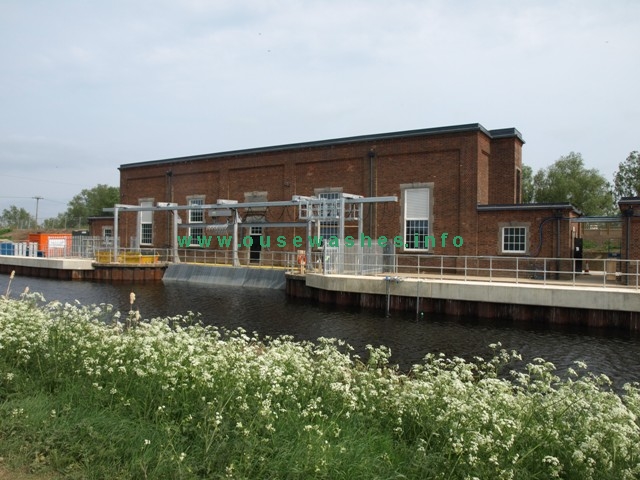 Photo: Eddy Edwards, April 2011
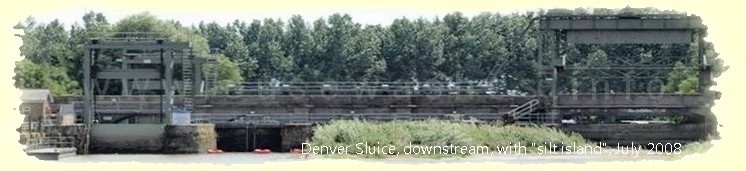
 This pumping station is at grid ref TL 471859 on the eastern bank of the northern section of the Old Bedford River (OBR) which is part of the Cranbook Drain/ Counterdrain/Old Bedford River (CD/OBR) system.
| If you are unfamiliar with or confused about the watercourses surrounding or adjacent to the Ouse Washes, my features page explains the overall situation on the rivers section, or go to my CD/OBR page for a more detailed account of this particular river. |
The Catchment board realised that they had two choices to avoid the possibility of the river overflowing the low west bank of the system and flooding parts of the Middle Level - either raise the bank or build a pumping station to remove excess water.
Work on 20 miles of banks was considered too costly, very difficult, and only a short-term solution because the weight of new soil on top simply pushes the bottom down further, a never-ending cycle. A station at the northern end, Old Bedford Sluice, would need to pump against high tidal heads and the whole channel particularly north of the Manea & Welney pump, would need improvement to contain the total potential flow of 750 tpm. A pump half way between the two IDB pumps meant that the maximun flow in the river would be 450 tpm from the south and 300 tpm from the north, and the head into the Delph much less.
The station was designed by the Catchment Board's own Mechanical Engineer, Mr WF Pattison, who sadly died before the project was completed.
Potted history
| period | engine: make model, type, fuel | rating hp | pump | tpm | m3/s note 9 |
acres drained |
discharge/remarks/other | refs |
| 1948-2011 | Allen 6S37C 6 cyl vertical 4 stroke diesel |
410-500 bhp | No. 2 set: Allen Conqueror 2 x 45"centrifugal twin-parallel branched to 72" |
375 | 6.3 | This engine donated to the Internal Fire, Museum of Power, Ceredigion, Wales | ||
| 1948-1998 | Allen 6S37 6 cyl vertical 4 stroke diesel |
410-500 bhp | No. 1 set: Allen Conqueror 2 x 45"centrifugal twin-parallel branched to 72" |
375 | 6.3 | engine of No 1 pump-set sold 1998, replaced with new Perkins | 5 | |
| 1998-2011 | Perkins 4006TG 6 cyl vertical 4 stroke diesel |
456 bhp | No.1 set: Allen Conqueror 2 x 45"centrifugal twin-parallel branched to 72" |
375 | 6.3 | The Perkins had automated starting & drove the original 1948 pump via a reduction gearbox. This was the main pumpset. | ||
| 2011 | 4 x Bedford Electric, each 2.5 cumecs |
Axial flow | 10 | a reduction of 20% from the 12.6 m3/s of the 2 diesels |
Diesel powered Pumping Station, 1948-2010
The original station was diesel powered. Two 'pump-sets' were installed by WH Allen, Sons & Co Ltd of Bedford, each consisting of an Allen engine driving Allen twin centrfugal pumps. The engines were 6-cylinder S37 diesels, each with a maximum rating of 500bhp at 475 rpm, but normal load required only 410bhp.
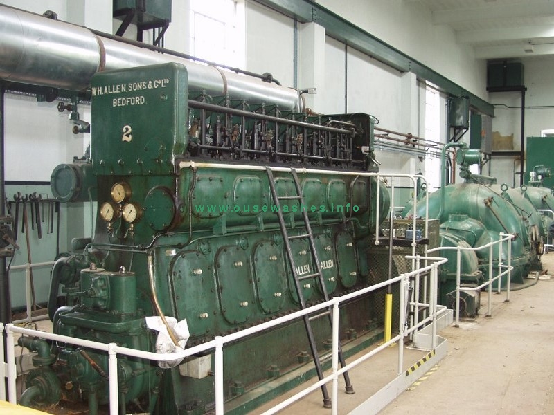 Photo: Internal Fire Museum of Power, Wales |
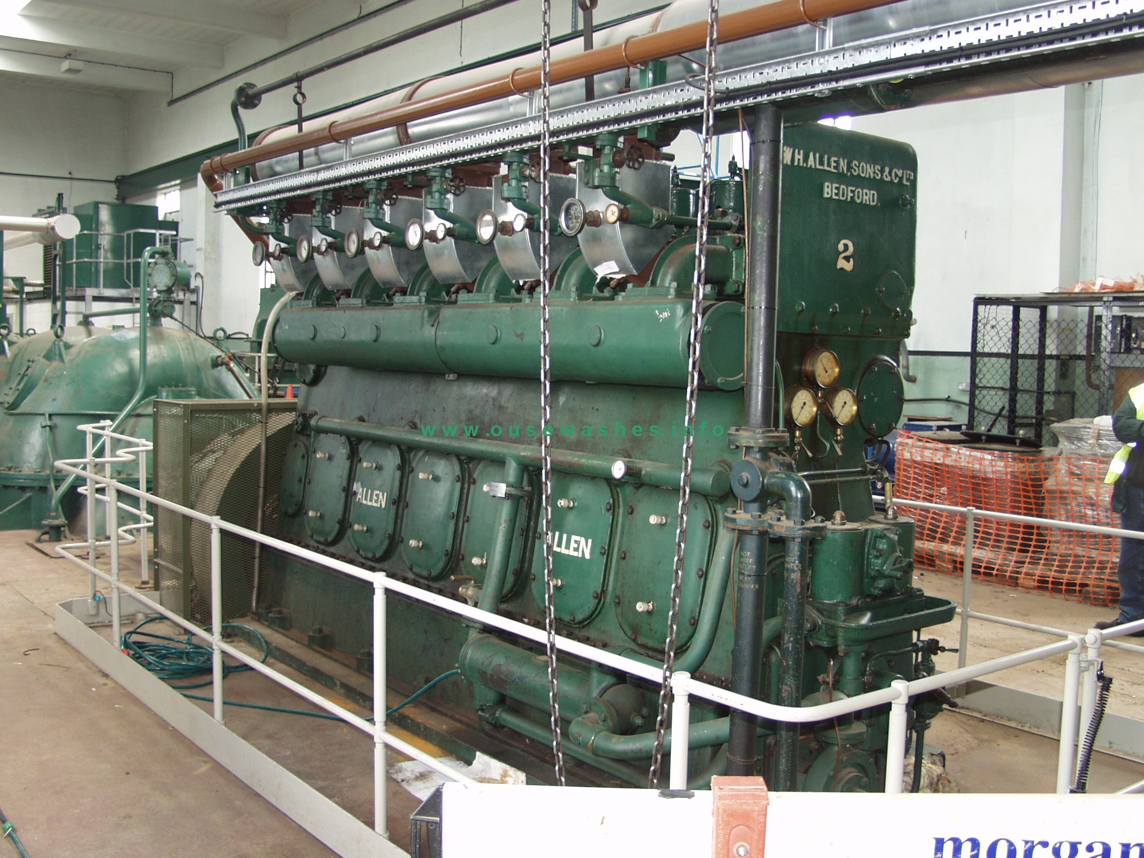 Photo: Internal Fire Museum of Power |
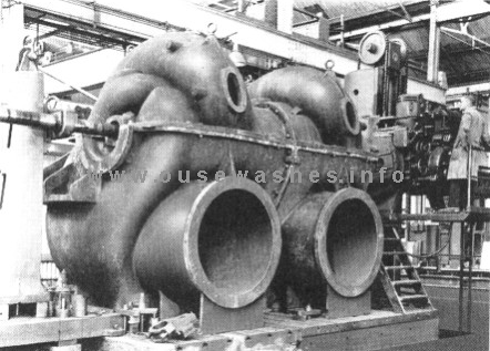 Photo: Bedford Pumps Ltd |
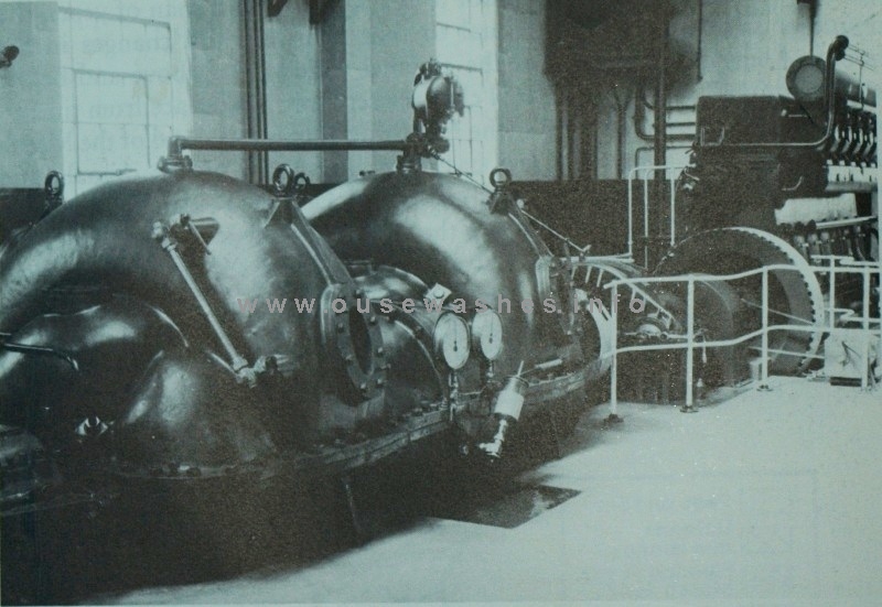 Photo: KSG Hinde, "Fenland Pumping Engines" |
Discharge out of the pump hall was controlled by the two tall electrically-driven sluice valves by the right hand wall. The two 72" pipes then went through the barrier bank discharging into the River Delph via
 Photo: Environment Agency |
manually operated flap gates
controlled from a small brick building (below) on the Delph side of the bank.
The Bailey Bridge gives access to RSPB hides on the barrier bank. 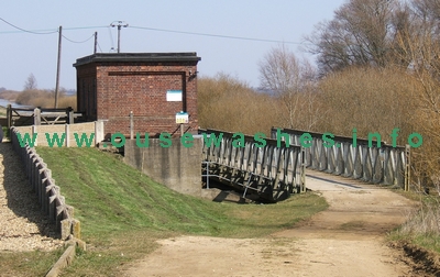 (Photo: Eddy Edwards, 2006) |
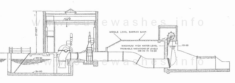
drawing from the The Allen Engineering Review, Feb 1949, (Courtesy of John Baker)
Note that the bottom of the sump here is shown as "94.00" and the water level as "103.50". These are measurements in feet above South Level Datum (SLD) which is 100 feet below the normal Ordnance Datum (OD). The sump bottom is therefore minus 6ft OD, (ie 6ft below sea level). The water level figure shown is that at which the station starts pumping. The bottom of the pump intake is not shown, but it is elsewhere as 97.50 (ft SLD).
Translating the figures to modern terminology, metres OD, the level at which pumping started was 1.15, and it stopped (I believe) at 0.75. In 2002 those figures were reduced by 5 cms (2 inches) to 1.10 and 0.70, perhaps allowing for a lowered bank height?
During the mid 1990s, a number of costly breakdowns of the ageing plant, plus the high cost of manual operation of the station (two men on duty at all times) led to an appraisal of the flood defence of the river system by consultants Binnie Black and Veatch (BBV) for the body then responsible for the river, the National Rivers Authority (NRA). Of the options considered, including new pumping stations elsewhere, the one favoured in 1996 was total replacement of the existing plant by four fully automated diesel-powered pump-sets with the same total capacity as the two current pumps but with greater flexibility and security during down-time. Electrical power was ruled out due to the high cost of bringing in supply-lines, high standing charges and need for power-failure back-up. The capital cost was put at £1.1 million.
However, the 1996 plan was apparently dropped, whether or not due to the management changing from NRA to EA, I know not, but suspect it was. Anyway, in 1998 the station was simply "refurbished"at a cost of £248,000, the majority of the cost being replacement of the Allen engine of number 1 pump-set with a new auto-controled Perkins 4006TG diesel contained within a tall metal cabinet seen at the far end in this photo. This was rated at 456hp and ran at 1500 rpm, much faster than the Allen, so requiring a reduction gearbox before connection to the original Allen twin-pumps.
In January 2003, only five years after the 1998 works, "both pumps failed" costing £105,000 for temporary pumping. An EA publication in 2004 stated
"highlighting the fact that the design configuration of the plant was complex, requiring a number of critical plant items working in series for a pump to start."Another problem was a spillage of 6,000 litres of diesel in 2007 due to a pipe failure.
Electric powered
Following another expensive appraisal in 2004, and the EA's Cranbrook/Counter Drain strategy report of 2008 both of which which considered all the earlier options and others, it was decided to "upgrade" and refurbish the pumping station in a £3.4 million project. This involved complete removal of the diesel engines and their pumps and ancilliary equipment, and replacement with electric powered equipment to give the station another 25 years life. (After which the station is planned to be de-commissioned and flood risk managed through flood storage reservoirs utilising mineral extraction pits.)The change to electricity seems odd as all the reasons for rejection in 1996 still applied, the fuel cost was higher than diesel, and somewhat worryingly, the maximum supply the lines can carry is limited to 1,000kVa resulting in a cut of 20% in maximum pumping capacity.
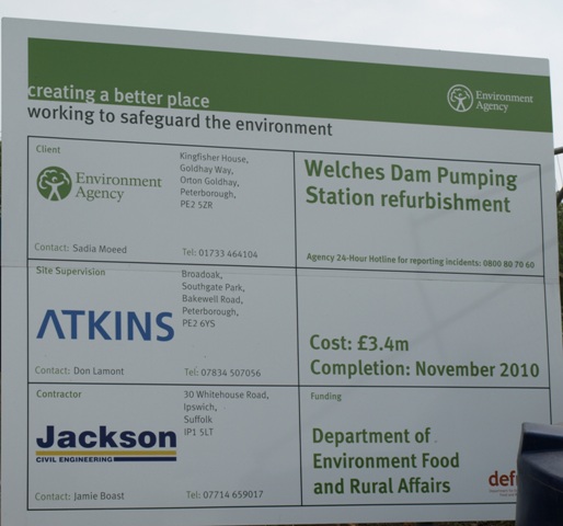
The main contractor was Jackson Civil Engineering (JCE), and Atkins were the consultants and provided site supervision. Work was scheduled for completion by November 2010.
Bedford Pumps supplied the new engines, pumps, pipework and control equipment.
By September 2009 JCE had completed:
• Strengthening works to the Bailey bridge on the discharge side of the pumping station;
• Installation of a platform and ducting for the transformer base in preparation for EDF energy to upgrade the power supply in autumn 2009; and
• Indoor modifications necessary for the power supply to be directed to the new pumps.
EDF energy upgraded the power supply, delivered and installed the transformer in autumn 2009, and completed their remaining tasks, laying the new cable, fitting a new pole and activating the new supply in January 2010.
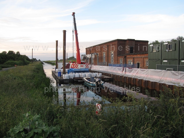 Crane on pontoon raft photographed by Hugh Venables in August 2010
The main refurbishment works were dealt with by JCE between May and September 2010 involving:
• Removal of the diesel engines, pumps, fuel pipe work, day tanks and associated control systems.
• Installation of four new 2.5 cumec axial flow pumpsets, syphon breaking valves, and discharge pipework. providing the same capacity as the diesel station.

The four new electric motors and pumps. (Photo: Eddy Edwards, 2013)
- Installation of motor controls and switchgear for the new pumps
- Installation of a new diesel standby generator with switchgear and fuel system.
- Replacement of the overhead gantry crane, the weed screen, and automatic screen cleaner.
- Installation of a new power supply with 11kV-400V 1000kVA transformer.
- River bank piling works.
- Repair works to the main pump house roof.
The pumpsets, pipework, control panel, instrumentation, cabling and stand-by generator were manufactured/supplied by Bedford Pumps Ltd.
The existing standard of protection, 1 in 25 years (4%) will be maintained. The refurbishment also increase the reliability of the pumping station and reduce the current operational and maintenance requirements as it will be fully automated. The new pumping arrangement will also increase the efficiency of the station.
Other works included replacing the original steel Crittall windows with 70mm white PVC-u double glazed units, Georgian insert and aluminium louvre panels by SEHBAC Commercial . During the works the pumping station was decommissioned and temporary pumping put in place.
Sources: Minutes of the EA Regional Flood Defence Committee Meeting Jan 2010, pages 38 and 39: Bedford pumps news bulletin.

Notes, sources and bibliograhy
| ref | notes, sources and glossary used in text and tables throughout this page |
| 1 | 2004 Cranbrook Drain/Counterdrain (Welches Dam) Strategy Study, SEA8 Scoping Report, by Atkins for EA |
| 2 | 2008 Cranbrook/Counter Drain Flood Risk Management Strategy, Appraisal Report |
| 3 | 2002 Ouse Washes Water Level Management Plan, by Halcrow for the EA |
| 4 | 1949 The Allen Engineering Review, Feb pp 6-15 (copy courtesy of John Baker, EA, Ely) |
| 5 | John Baker, Operations Engr, EA, Ely |
| 6 | 1996 Counter Drain Flood Defences, Gt Ouse LFDC inspection, May, Executive Summary of Appraisal Report (the appraisal was by Binnie Black & Veatch for NRA) |
| 7 | 1997 Welches Dam PS Engine Replacement Project Appraisal Report |
| 8 | SEA= Strategic Environmental Assessment |
| 9 | m3/s = cubic metres per second, commonly called cumecs |