The
|

|
Welcome to my independent research project on
at
Hundred Foot Pumping Station
Introduction
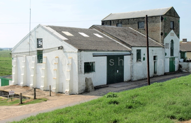 This pumping station, or "engine", a couple of miles north of Pymoor, sits just a few feet from the B1411 road
on the eastern side of the South Level barrier bank and the Hundred Foot/New Bedford River. It was built in 1830 to replace
wind drainage-mills.
This pumping station, or "engine", a couple of miles north of Pymoor, sits just a few feet from the B1411 road
on the eastern side of the South Level barrier bank and the Hundred Foot/New Bedford River. It was built in 1830 to replace
wind drainage-mills.Photo: EE, June 2010, looking s-w from the bank of the 100 Foot River
It is owned and operated by the local drainage authority, the Littleport & Downham Internal Drainage Board, which is responsible for draining 13,000 hectares (32,000 acres) of the South Level, and is the largest member of the Ely Group of IDBs.
I've long had an interest in this place, having driven past it to and from work for several years, but it wasn't till early 2010 that I had time to stop and look around and take some photos. I was hooked, and soon posted a web-page about it based on my own observations and web research. That led me to look at other structures around the Washes followed by the launch of this website in 2011. In May 2013 Chris Holley found my site, contacted me and later introduced me to John (JS) Martin, a member and ex-chairman of the IDB who kindly provided documents and gave a guided tour of the station which enabled me to completely re-write the page. Since then the ex-Chief Engineer of the IDB, Tony Goodge, has kindly provided yet more information and some previously unpublished plans and photos from his collection. Along the way a number of other visitors have made small but valuable contributions, and I am greatly indebted to all who've helped.
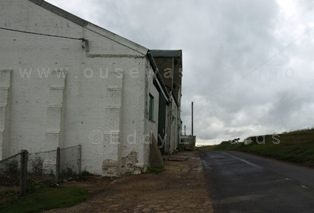 What you see as you drive past are the large original buildings close by the road, once part of the coal-fired
steam-powered station. The steam
engines have long since gone and the buildings are now used as workshops and for housing a stand-by diesel engine with its pump
and oil tanks.
 Photo: EE, Aug 2011, viewed from the north showing how close the station is to the road
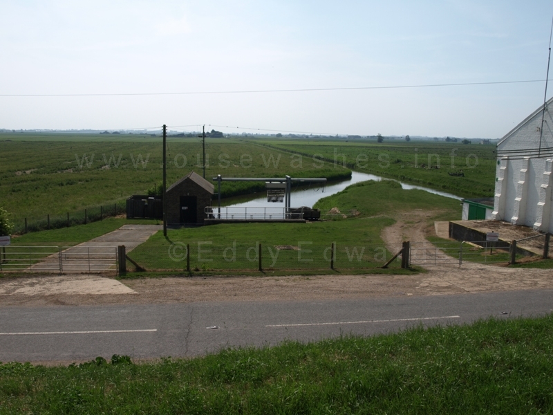 What you may not notice at first is a small modern unprepossessing building further away and below the road - part of the "New" electric-powered
pumping station used today.
What you may not notice at first is a small modern unprepossessing building further away and below the road - part of the "New" electric-powered
pumping station used today.Photo: EE, June 2010, the electric station seen from the top of barrier bank.
To appreciate the vast size of old buildings and appreciate the spread of this station, you need to walk along the footpath just outside the northern edge of the site, and look back from beyond where the intake drain splits into two channels, where you will see the view below, although now high metal-staked security fencing surrounding the area spoils the view.
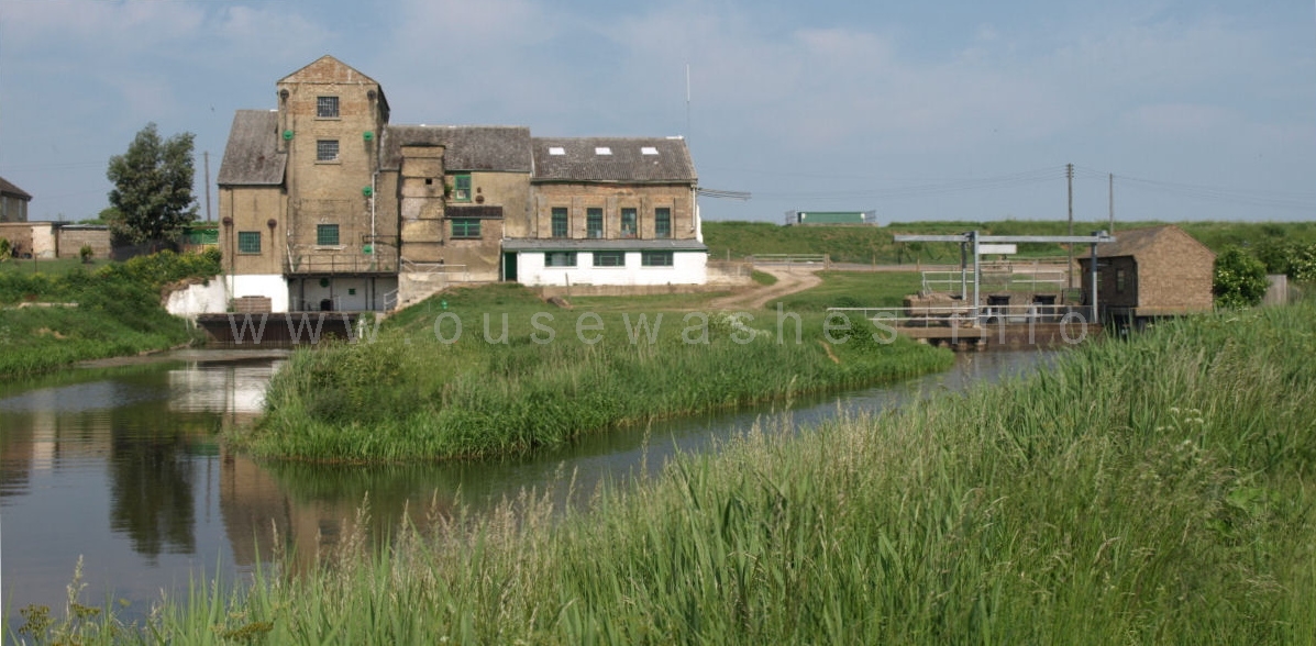
Photo: Peter Cox, June 2010, looking n-w
Left and centre are the buildings of the old steam/diesel station, on the right the "New" electric station.
Left to right
- Manager's house & garden (now privately owned)
- (Scoop) Wheel house
- Intake and weed grill below
- Engine house, 3 stories
- more of Intake grill below.
- Lower sections of chimney
- Boiler house behind.
- Workshop (once the coking shed) with a lower store or workshop in front.
- Access track for weed-cart.
- Green covers (on top of the 100 Ft river bank) over the syphon valves on the new discharge pipes.
- Intake grill with automatic weed grab above it.
- Black pipes above grill cover electric pumps and motors
- Control house
- electricity sub-station, part hidden by bush.
Note roofing on the old station. Engine house is slate tiled but other buldings appear to have corrugated asbestos sheets which were not produced until the 1920s, I wonder what the original roofing was?
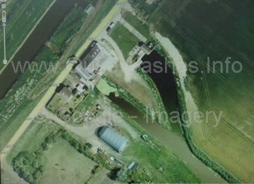
This satellite view by Google shows the tidal 100 Ft
river left-centre to top. The IDB's drain, coming in from bottom right shows the original intake cut in 1830 and the branch forking off towards the top cut in 1926.
Potted history
| period | engine | type | rating | pump | tpm | m3/s | discharge/remarks/other | ref |
| 1756-1830 | wind | scoopwheel | ||||||
| 1830-1844 | Butterley |
steam beam |
80hp |
scoopwheel 37'5"diam |
||||
| 1844-1882 | Butterley |
steam beam | 80hp | scoopwheel 41'8"diam |
||||
| 1882-1914 | Butterley |
steam beam | 224hp | scoopwheel 50'0" |
scoopwheel weighed 75 tons | |||
| 1911 | all 3 boilers replaced by high press're Lancashires | |||||||
| 1914 | Butterley beam engine & scoopwheel scrapped. | |||||||
| 1914-1950 | Gwynnes |
Steam vertical |
400hp | centrigugal Gwynnes 50" | 212 | |||
| 1926-1965 | Mirrlees | Oil (diesel) 5 cyl vertical 4 stroke blast injection |
230hp | centrigugal Gwynnes 36" | 110 | supplementary engine installed in new house, with new intake on new spur from drain | 1 | |
| 1950 | Chimney removed in Sept | |||||||
| 1950-now | Ruston- Hornsby 6VEBX |
Oil (diesel) 6 cyl vertical 4 stroke |
540hp |
centrigugal Gwynnes 50" (the 1914 pump) |
200 | replaced Gwynnes steam engine Stand-by since 1985 Emergency use Dec 2012 |
4 3 6 |
|
| 1965 | Mirrlees | Oil (diesel) | engine sold | |||||
| 1985 | Mirrlees h'se demolished | |||||||
| 1985 | old steam station made Grade II* listed building. | |||||||
| 1986-now | 3 x Flygt | Electric submersible |
300 tot | tot 1.7 |
Near site of Mirrlees with same intake channel. 3 new discharge pipes |
1 | ||
| 2002 | old sluice gate at end of original discharge point, now serving the Ruston, removed and replaced by metal flap gates (7) | |||||||
| ref | source |
| 1 | Littleport & Downham IDB: Hundred Foot Pumping Station, KSG Hinde, 1987 |
| 2 | Littleport & Downham IDB: A Chronicle, AT Goodge, 1995 |
| 3 | Littleport & Downham IDB: Information leaflet, AT Goodge, 2003 |
| 4 | Landmark Publishing: Fenland Pumping Engines, KSG Hinde |
| 5 | Mr Hinde quotes 540 bhp; the website RealDiesels.co.uk quotes 650bhp at 500rpm (540bhp for the 5-cyl version) |
| 6 | Littleport & Downham IDB: minutes of meeting Feb 2013 |
| 7 | A.T.Goodge, ex-Engr to L&D IDB |
back to contents
Steam
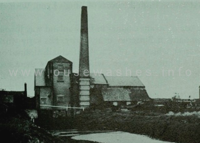 The pumping station was
built in 1830 to a design by Joseph Glynn of the Butterley Company of Derby.
Glynn also designed the original Butterley 30hp beam engine.
 The engine was virtually the same as the restored one at Stretham Old Engine.
On right, the rear intake-side of the steam engine buildings seen c1935
from photo by PLL Keiler or Keiller
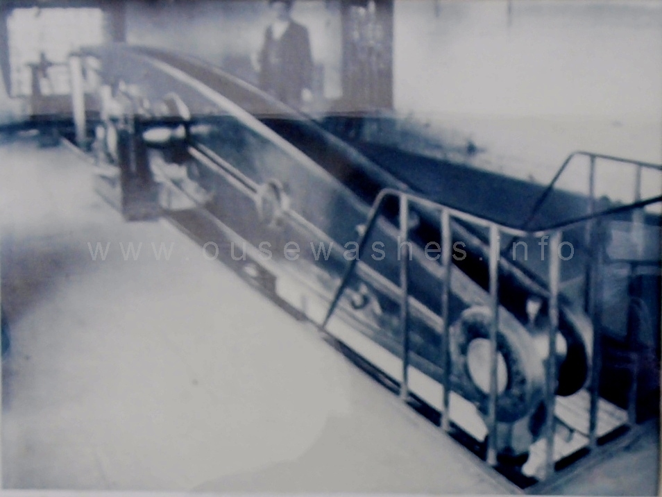
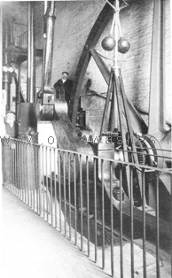 Images left and right are taken from photos displayed on wall of engine room.
Left is the 26ft 3in diameter flywheel and centrifugal governor, c1913.
On right the 26ft long beam of the Butterley engine.
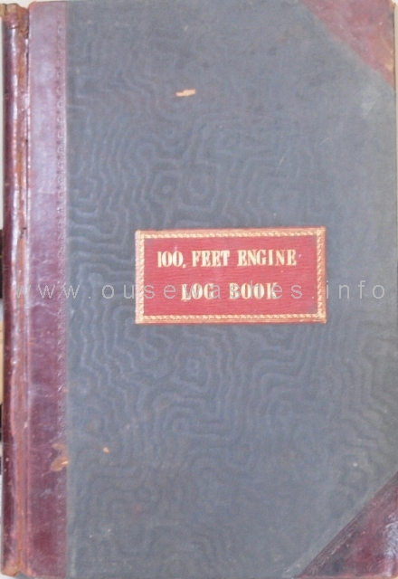
The men in charge of the steam engines (and usually the whole plant) were known as 'Engine-drivers' and they kept a daily log of running hours and coal consumption, often in beautifully bound books such as this one.
Most logs provide interesting figures. For instance, here in the year April 1841 to March 1843 (presumably a wet year) the engine was run on 192 days and 96 nights, a total of 3729 hours, and 1,397 tons of coal were delivered. In Oct 1861, the log shows that on the 22nd nearly 76 tons were received from Captain Cooper, at a cost of 15s 6p per ton plus 6d a ton for porters.
Glynn and Butterley supplied package deals of plant and buildings to many of the early steam-engine stations in the fens. Glynn is sometimes confused with Gwynne, a family-owned company that built the second steam engine here (see below) which wasn't founded until 1849. Even the citation on the English Heritage site is wrong in that respect.
It was the District's second steam engine, replacing (one of ?) seventy-five windmills in the area which apparently hadn't been able to cope with the heavy rains of 1824.
It was built with gault bricks on a raft of 600 piles with 300,000 bricks (source: English Heritage as above).

Photo: Peter Cox, Aug 2011
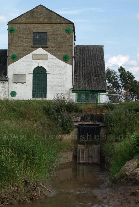
The discharge side seen here from the west bank of the river after a long trek from Suspension Br. Front of engine house (left) and wheelhouse and discharge into the tidal river. There are two gates, can't tell if flap or lift, or whether one or both are used.
Photo: Peter Cox, June 2011
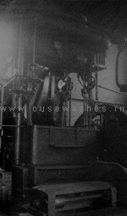
Gwynnes 1914 engine seen in 1949
(from Mr Hinde's book)
In 1911, the three boilers were replaced with high-pressure Lancashire boilers. I don't know whether this was because the old boilers, two of which were 42 years old and the third 36 years, were simply worn out, which is quite possible, or whether it was the first stage of plans to completely re-equip the station. Anyway, three years later, in 1914, the Butterley beam engine and scoopwheel were replaced by a vertical steam engine, by Gwynnes of Hammersmith in West London, coupled to a Gwynnes 50-inch centrifugal pump situated in the old wheelhouse. Perhaps if the boilers hadn't been replaced, the Board may have decided to convert the plant to oil like the one at Methwold & Feltwell in 1913.
The station was fuelled by coal, presumably brought up the tidal Hundred Foot River by fen lighters from the port of King's Lynn, and discharged by hand, labourers barrowing the coal over the bank and into the coal yard or coking house north of the boilerhouse.
| Buldings can often tell you a lot about themselves. The wall plates tell us who made them 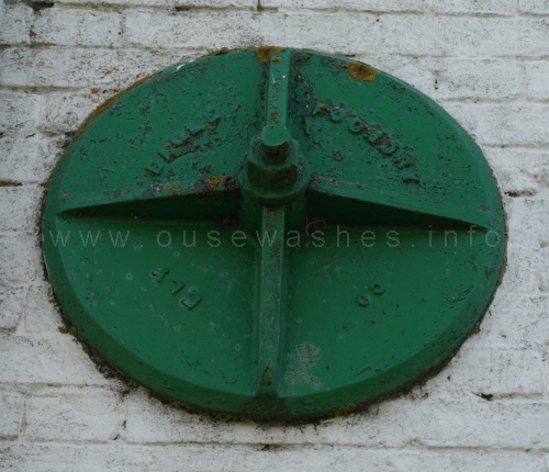 the "Eagle Foundry Co Ely". Unfortunately their offices at 6a Downham Road Ely are now those of a distance learning centre for dental nurses. |
| The height of the wheelhouse roof has changed three times. If you look closely you will see a line on the engine house wall about 1½ feet above the current roof, and I assume that would have been the original height in 1830. Much easier to see from the change of brick colour, is the position the roof was raised to in 1882 to accomodate the larger wheel. (Also note the two top-floor windows in the side of the engine house that had to be bricked up then.) I don't know when or why the roof was lowered, maybe in 1914 when the scoopwheel was replaced by a pump? |
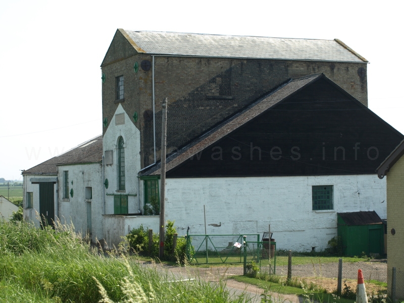
Photo: Peter Cox, June 2010, looking north
Note the green "lean-to" on the gable wall. More about that further down.
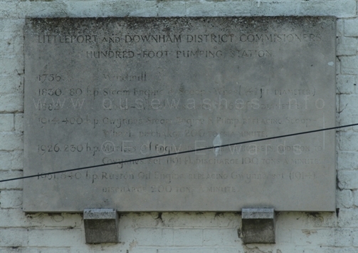
Photo: Peter Cox, June 2010
Above the arched window of the engine house roadside gable-end (see
above centre) a stone is inset inscribed with a now much quoted rhyme.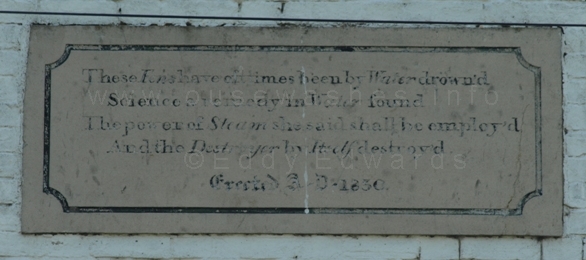 Photo: Peter Cox, June 2010 |
Science a remedy in Water found
The powers of Steam she said shall be employ'd
And the Destroyer by Itself destroy'd"
Erected A.D. 1830.
back to contents
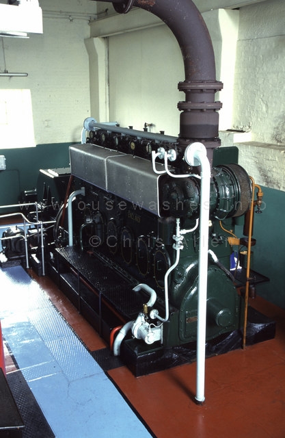
the Ruston engine seen in 1996
Photo by Chris Allen, Geograph.org.uk/photo/1031582
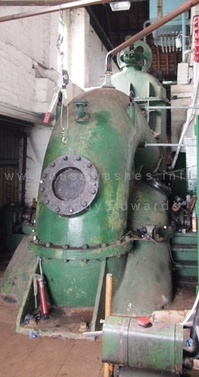
the 1914 50-inch Gwynnes pump in the scoopwheel house. It towers above the door to the left
Photo: Peter Cox, July 2013
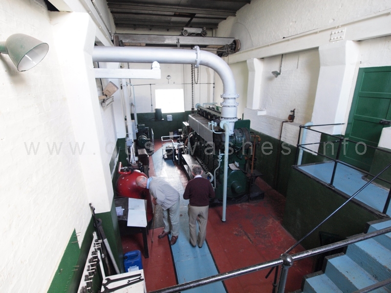
Photo: Peter Cox, July 2013 - click for close up of the engine
Above, Mr JS (John) Martin, a member and ex-Chairman of the IDB Board is examining the work log. There are very few changes compared with the scene 17 years earlier (photo on left).
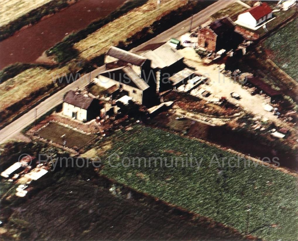 Aerial view of the station c1971.
Photo: was on the CCAN/Pymoor archives but now unavailable there.
According to the citation on the English Heritage page made when the station was listed in Feb 1985, the paved second floor of the steam engine house and stair was intact; and the lower galleries had been removed.
The old Lancashire coal-fired boilers that fired the steam engine have been retained and converted to store the diesel fuel.
back to contents
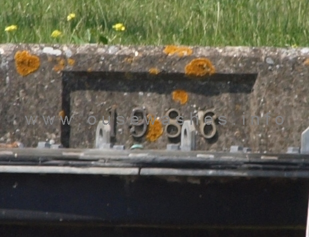
Date above intake pump housings
Photo: Peter Cox, July 2013

satellite view c2012 by Google
Tidal river left centre to top. IDB drain bottom right divides into two intake channels, the new one above.
Electric
Electricity took over from diesel in 1986. The 1926 building at the head of the second cut that had housed the Mirrlees diesel engine was demolished (the engine was removed earlier, see above) and the "New Hundred Foot Pumping Station" built to the south-east of the Mirlees House, i.e. further away from the road.The oft-quoted statement that the new electric station was built on the Mirrlees site seems incorrect when comparing the satelite view on the left with the c1971 aerial photo on the right (the latter was on the CCAN/ Pymoor Community Archive website in 2010 but unavailable there in 2013).
A new intake was constructed in the channel that had served the Mirlees, with three submersible Flyght motors and close-coupled pumps. A control building and electricity sub-station were constructed alongside,
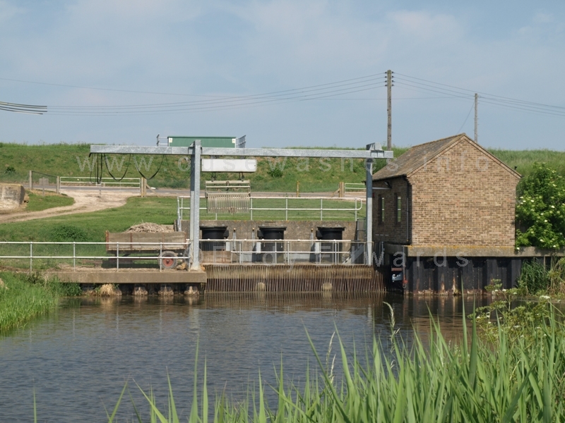
Driving past the site it is easy to miss the New Station. The only signs are a small nondescript brick building, a couple of poles and an odd looking steel structure above the end of a drain.
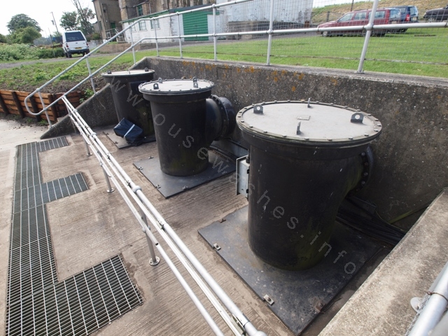 Housings for the electric pumps cannot be seen from the road.
Photo: Peter Cox, July 2013
|
Modern sophisticated weed grab discharges into a rather unsophisticated old farm cart. 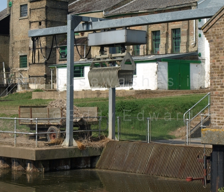 Photo: Peter Cox, June '10
Don't stand near the cart - the grab can start up without warning at any time |

Photos: Peter Cox, June 2010
Above is the New Station as seen from Hundred Foot River bank. The gate and track on the left leads to the sub-station with its wooden fencing. The small brick building is the control room, and the steel structure is a weed grab. Below that, and hidden from the road, are three steel pipes housing the powerful electric motors and pumps.
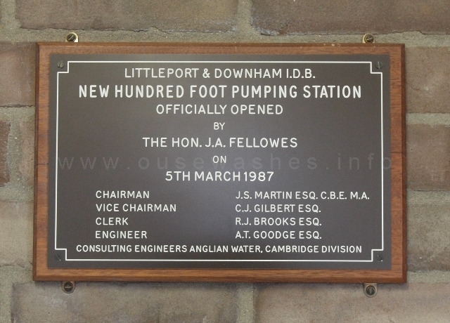 Plaque inside control room commemorating the official opening March 1987
Photo: Peter Cox, July 2013
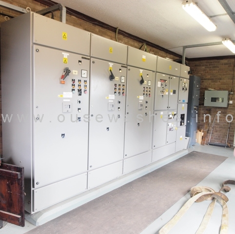
inside the control house
Photo: Peter Cox, July 2013
 Photos: Peter Cox, June 2010
Building the New Pumping Station
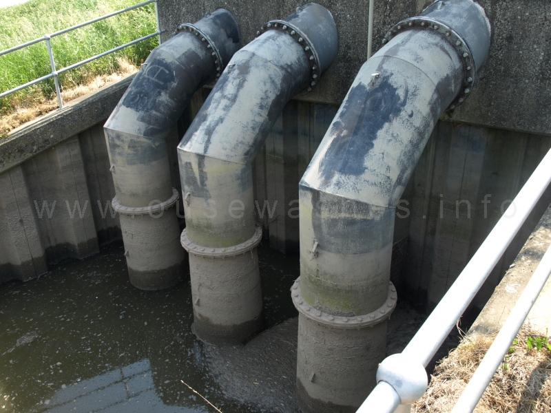 Photo: Peter Cox, June 2010
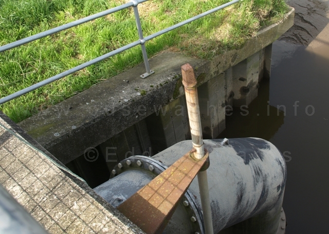
Photo: Peter Cox, Apr 2012
top of slacker control rod
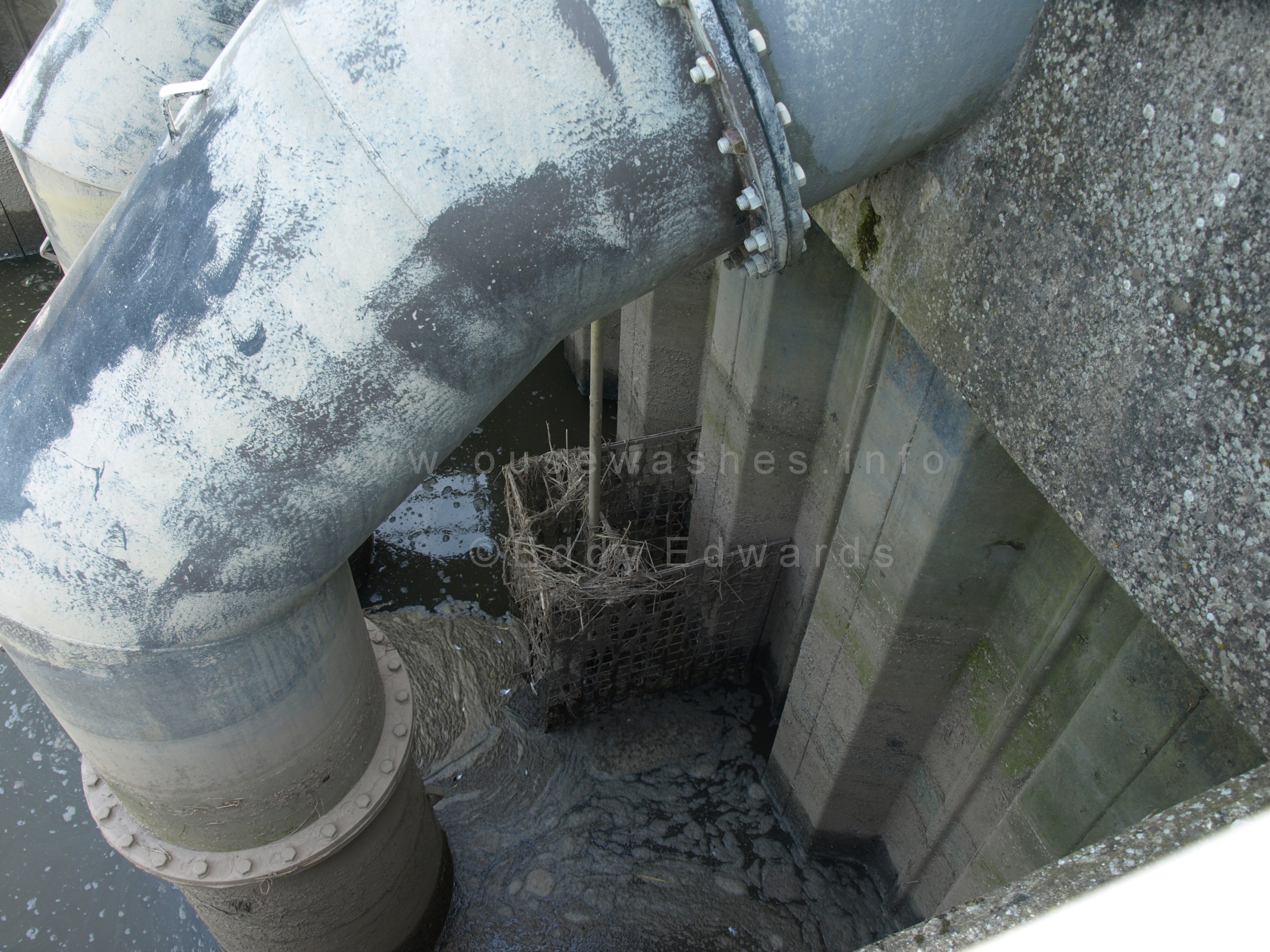
Photo: Peter Cox, Apr 2012
weed grill around inlet slacker
Discharge pipes and Irrigation Slacker
Across the road and over the river bank can be seen the three huge discharge pipes. A syphon-breaker valve is built into each pipe to prevent water flowing from the 100 Foot River into the IDB drain when the pumps are not operating. The valve chamber is covered by the green plastic (GRP) housing.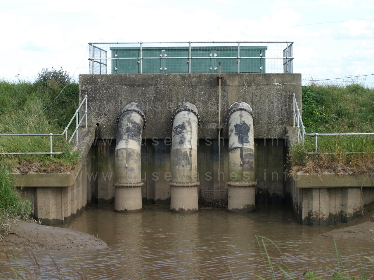 Photo: Peter Cox, June 2011
Photo above was taken from the far bank after walking from Suspension Bridge en route to the railway viaduct.
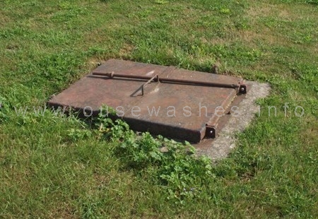
Photo: Peter Cox, July 2013
access to irigation divertor valve.
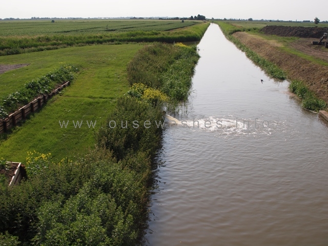
irigation outlet into old channel seen from back of old station.
The "new" channel is at far left
Photo: Peter Cox, July 2013
When opened, water flows through a 10 inch pipe to a point in the grassy area about half-way between road and the new intake where there is a manhole cover giving access to a diverter valve allowing discharge into into the old channel (see photos) or into a field drain to the northeast.
back to contents
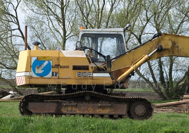
Liebherr R902 tracked excavator
II guess mid 1980s-90s vintage with a very, very long reach!
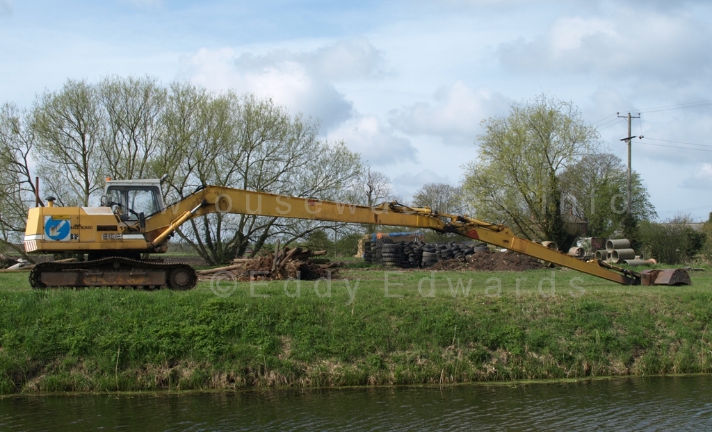
at 51ft, this is probably the longest reach in the South Level
Photos: Peter Cox, Apr 2012
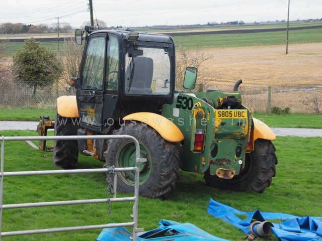
Photo: Peter Cox, Dec 2012
1998? JCB 530-70 Loadall
here fitted with lifting forks on front.
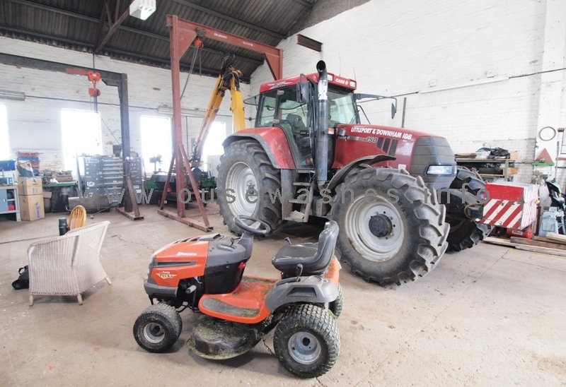
Photo: Peter Cox, July 2013
Tractors large and small.
Case CVX150 (early 2000s?) with rear attachment
and a Husqvarma ride-on mower
Plant & Machinery
TThe IDB have some impressive equipment for maintaining their 193 miles of drains spread over 30,000 acres (2003 data, source: ref 3 in table above).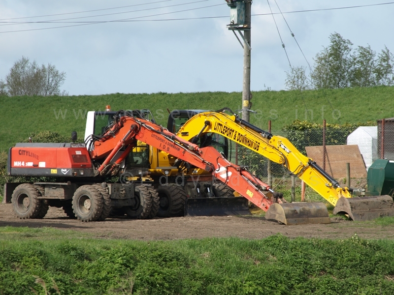
Photo: Peter Cox, Apr 2012
A pair of wheeled excavators
The nearest is a 2001-ish German built O&K MH4,5 Cityline, weighing in at about 13.5 tons, with a 9.4m reach.
The yellow one is newer, a British JCB JS145W with monoboom and front dozer blade fitted, weighing about 14.5 tons and probably an 8.5m reach
back to contents
| There's a video on You Tube of the same age and model of engine which says it is turbo charged and air-started. You can see it running here |
December 2012 emergency actions
Very heavy rainfall in the UK during Oct-Dec 2012 resulted in waterlogged fields and potential flooding over much of the country.In the South Bedford Level where much of the land is below mean sea level, the drainage authorities faced difficult times. At this pumping station auxilliary pumps were brought in just before Christmas and the old Ruston was also used to help kep the IDB system drained.
I am very grateful to two site visitors for advising me of this:
On 26th Dec 2012 Tony Mitchell of Pymoor e-mailed
"the 'redundant' diesel engine was used to lower the level in the pound by over a metre when despite the use of auxiliary pumps (necessitating the closure of the road for their output hoses) the drain levels were increasing - in view of the frequency of power cuts in the pymoor area and the impracticallity of providing generator capacity to power the electric pumps it is important to the whole of the South Bedford Level for the Ruston diesel to be maintained in a state of readiness (which apparently it was not - someone had to be asked to get it running)."

Auxillary pumping, Dec 2012
Photo: Richard Humphrey, Dec '12
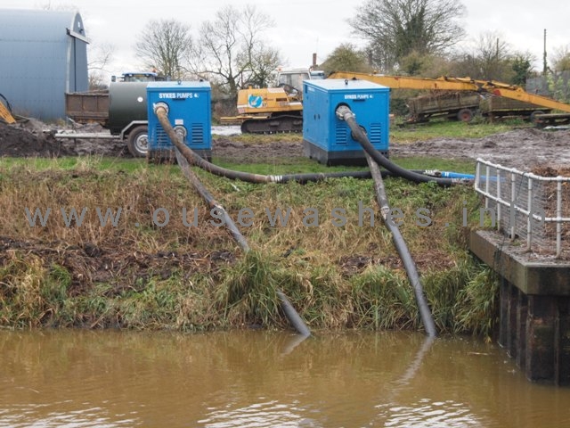
Auxillary pumps, Dec 2012
Photo: Peter Cox, Dec '12
"Are these additional pumps to cope with the volume of water or do they have a breakdown/maintenance situation ?"When I visited the site on the afternoon of 28th Dec, the hoses had been moved off the road but two Sykes diesel pumps and a fuel bowser were still in position and the hoses ready for re-connection. The pumps looked like the Wispaset 150 model, a slienced pump capable of pumping 324m2/hr.
The only people on site then were two maintenance men checking the operation of the weed-grab, so as yet I have no answers to the comments above. If anyone has, I would appreciate an e-mail.
back to contents

List of Engine Drivers displayed in the Station.
Photo: Peter Cox, July '13
Tony Mitchell and Richard Humphrey raised a number of questions above about the problems in late December 2012.
At the Hundred Foot, the situation was exacerbate because one of the electric pumps was away for repair, reducing pumping capacity to 200 tons/ minute.
are contained in the minutes of the IDB's meetings in February and May 2013. To summarise, in my words,:
- December 2012. One of the three electric pumps was away for repair (reducing electric pumping output to 200 tons/minute)
- 19th-20th, heavy rain, 25.3mm (1 inch) in 2 days
- 21st, attempts made to start the Ruston but pump could not be primed. Temporary pumping equipment sought.
- 22nd, more heavy rain 16mm (0.6 inch). Two 6-inch portable pumps deployed
- 23rd, Gary Miller, an ex-employee of the Board, attended site (having been contacted the previous day) to assist with starting the Ruston. Now, Gary knows a thing or two about the Ruston and its pump. Not only did he work on both, he was born and bred next door, his father Donald being the Engine Driver for more than 20 years (see photo right). Some issues were found with engine and pump, but further investigations found the intake channel was badly silted.
- 24th, am, channel desilted (with help including some Board members)
- 24th, at 1700hrs the Ruston was started and ran for 3 hrs (pumping at the same capacity as the two working electric pumps together). Levels reduced by over a metre.
- 27th Dec Portable pumps switched off.
Reading between the lines, I think the Board were somewhat concerned about the circumstances have learned lessons and will implement procedures to reduce future problems.
back to contents