Pumping Stations in the
South Level
a companion site to the
Ouse Washes Website
(Old) Ten Mile Bank Pumping Station
INCOMPLETE DRAFT, Revision 1Introduction
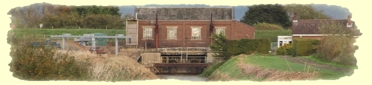
The earliest steam engine in the South Level and only the second in the Fens, was erected on the west side of the Great Ouse River, 1½ miles south of Denver Sluice, to drain the northern part of the L&D IDB's area. The river here is also known as the Ten Mile River and the road alongside, and also the nearest village, are both named Ten Mile Bank, after whch the station was named. (Hinde says early references name it Modney Court, but I haven't found that yet). Steam continued to be used, or to be available for use, until 1948Potted history
| period | fuel | engine | rating hp | pump/discharge | tpm | m3/s | head | acres drained |
discharge/remarks/other | refs |
| 1820-1842 | steam | Hague&Topham | 30 |
2 x scoopwheels 26ft x 2ft. One used at low water in Ouse, other at high |
Hse demolished, plant sold 1842 | 3,2 | ||||
| 1842-1912 | steam | Butterley | 80 | new scoopwheel. extended to 43'8" diam & 3' wide in 1878 |
new house like 100Ft | 3 | ||||
| 1912-1948 | steam | 2 x Allen double- acting condensing 3 Lancashire boilers |
250 each |
2 x Allen 48" horizontal-spindle centrifugal pumps | in truncated 1842 hse | 3,2 | ||||
| 1935-1995 | diesel | Allen 3S60 3-cyl, 4-stroke 238 litres 4 |
340 | replaced 1 steam eng. Last worked Feb 1977 |
3 4 |
|||||
| 1948-1995 | diesel | Allen T47 4-cyl, 2-stroke 124 litres 4 |
360 | replaced other steam Last worked Feb 1977 |
3 4 |
|||||
 Photo: Cambs Coll via Hinde
 the 1842 steam plant seen c1900
 Photo: Courtesy Tony Goodge, ex-Engineer of L&D IDB
Interior of the station in 19xx showing the diesel-powered plant. At centre rear is the 1935 Allen 3S60, 340bhp 3-cyl 4-stroke diesel, and on the right is the 1948 Allen T47, 360bhp 4-cyl 2-stroke diesel.
Can't tell from this whether the rear engine is running, but the front one, the T47, is definitely not because the slots/ grooves in the huge flywheel (between white hand-rails) can be seen clearly. Before use, the flywheel has to be turned manually to a starting position by engaging a bar in the slots and levering it around using the stand in front of it as a fulcrum, an operation known as "barring".
After the site was decommissioned, both engines were put into storage and subsequently taken to Prickwillow Engine Museum where they were rebuilt and painted. They are now on display there (see below) and regularly run. Some covers have been left off to enable visitors to see operation of some parts and the exaust and cooling pipes have been changed to suit the new location. Below right, the T47 flywheel slots are not visible indicating the engine was running.

above and right, 3S60

above and far right, T47
 |
 Photos: Eddy, 2013 Left, 3S60; right, T47 (note changes from above.) |
References and Bibliographyh3>
| ref | notes, sources and glossary used in text and tables throughout this page |
| 1 | ELY Group of IDBs website |
| 2 | KSG Hinde: Fenland Pumping Engines, Landmark, 2006 |
| 3 | Littleport and Downham IDB - A Chronicle. (History of the IDB) by AT Goodge, Engineer to the Board, 1995 |
| 4 | Prickwillow Drainage Engine Museum information boards |
| 5 | |
| 6 | |
| 7 | |
| 8 |
back to top of page