The river and its sources
The river has three sections all with a different name.- First Cranbrook Drain, which receives gravity flow from 6,440 acres of "highland" around Somersham, principally from the sewage treatment works
- Next the Counter Drain, which receives water pumped into it from 11,630 acres of low-lying Inland Drainage Board (IDB) area of Sutton & Mepal
- Lastly the Old Bedford River (north), which receives the pumped discharge of another 7,680 acres of low-lying IDB, Manea & Welney
The river is within the catchment area of the River Great Ouse (RGO), and managed by the catchment's board.
The Counter Drain and Old Bedford sections have a high east bank and low west one. The system in non-flood conditions flows to the Old Bedford Sluice at Salters Lode where it should (but often can't) drain into the "Tidal River" (a stretch of the River Great Ouse).
Flows were quoted in a 1949 document4 as 150 tons per minute (tpm) gravity, and 300 tpm from each IDB.
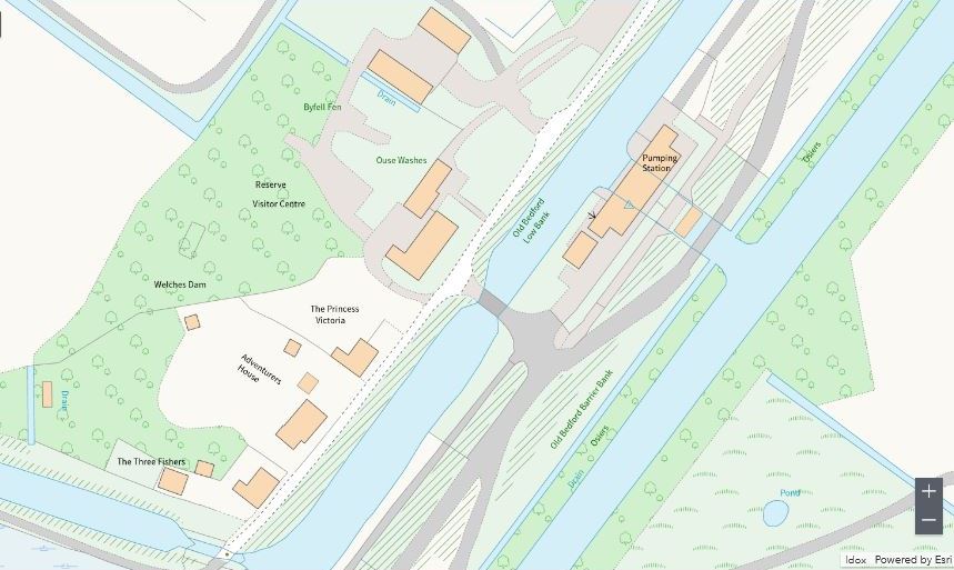
If you are unfamiliar with or confused about the catchment watercourses surrounding or adjacent to the Ouse Washes, my features page
explains the overall situation on the rivers section, or go to my
CD/OBR page for a more detailed account of this particular river.
Concerns of bank failure and flooding
The eastern bank is high being also the Middle Level Barrier Bank (MLBB, the western bank of Vermuyden's Hundred Feet/Ouse Washes flood reservoir). The floods of 1937 almost overtopped the MLBB and work was soon put in place to raise it by 2 feet 6 inches, breasted with clay, for most of its 18 miles.The west bank by contrast was low and weak in places but remained untouched. The Catchment board realised that they had two choices to avoid the possibility of the river overflowing the low west bank and flooding parts of the Middle Level - either raise the bank or build a pumping station to remove excess water.
Work on 20 miles of banks was considered too costly, very difficult, and only a short-term solution because the weight of new soil on top simply pushes the bottom down further, a never-ending cycle.
A station at the northern end at Old Bedford Sluice pumping into the Tidal River would need to pump against high tidal heads and the whole channel particularly north of the Manea & Welney pump, would need improvement to contain the total potential flow of 750 tpm.
A pump half-way between the two IDB outlets, discharging into the Delph River running alongside to the east would mean that the maximun flow in the river would be 450 tpm from the south and 300 tpm from the north, and the head into the Delph much less.
Solution - a pumping station at Welches Dam
The "half-way" idea was the chosen solution and following Ministry approval (from Ministry of Agriculture and Fisheries) the river was declared a "Main River" (which I think aids funding). A site at Welches Dam was selected and a pumping station was designed in-house by the Catchment Board's Mechanical Engineer, Mr WF Pattison. Sadly Mr Pattison died before the project was completed.It was commissioned by the River Great Ouse Catchment Board, and work soon began. As it did in those days.
Scroll down to follow the progress, or choose a subject from the index. (To open: press firmly and hold, then tap a subject; or hover mouse. You can return to the index anytime via button on left.)
Welches Dam Pumping Station
Diesel powered, 1949-2010
Station specifications
Buildings- main engine room or pump hall approx 106 feet long by 33½ feet
- annex at the north end with mess room and store room
- annex at the south, battery room and boiler room for c/heating
- separate 34ft long oil storage house to the south with 3 cyl tanks, total 15,000 galls
- separate valve house on the east, with 2 x 72inch flapgates
All had to be piled. Nearly 300 14 inch by 14 inch reinforced conrete piles of various lengths up to 33 feet were driven down
Electricity
No mains supply available so a number of small generators were specified.
- 18kW Allen DC driven by 30hp Lister diesel for lighting heating and power.
- Two 1.5kW Allen DC generators driven from the main engines
- 3kW Allen DC driven by a 7hp Lister as an auxillary system with battery storage for heating and lighting when main plant not operating.
Bridge and station retaining wall
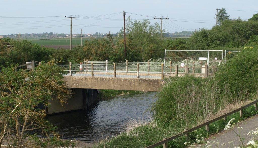 The first work was to build a bridge across ther river for access to the construction site between the river and MLBB, a 34-feet single-span concrete structure with steel sheet pile abutments replacing the earlier one which probably dated to the 1650s.
Steel-sheet piling retaining wall in front of the station was also installed, all completed in February 1946.
Photo: Peter Cox, April 2011, Olympus E-410
Cranes
Steam driven site crane7½ ton capacity with a chain-controlled 100 foot lattice jib erected on barrier bank in March 1946 and in continual use until August 1948 when it had to be dismantled in order to set the discharge pipe 2 through the bank.
Hand-operated site crane
used to asemble the steam crane
Overhead crane in pump hall
Hand-operated Herbert Morris 10-ton travelling crane
Pumping machinery
PumpsTwo Allen 'Conqueror' 45-inch twin-parallel centrifugal double-suction units, one left-hand, one right hand, each capable of pumping 375 tons/min against an 11 feet head
Engines
Two 6-cylinderAllen S37 4-stroke diesels, each with a maximum rating of 500bhp at 475 rpm, but normal load required only 410bhp.
Gearboxes
Each engine connected via a 2.2 : 1 reduction gearbox to a shaft driving the pump
Pumps, engines and gearboxes designed as "sets" by WH Allen, Sons & Co Ltd of Bedford but able to be split for delivery, as below
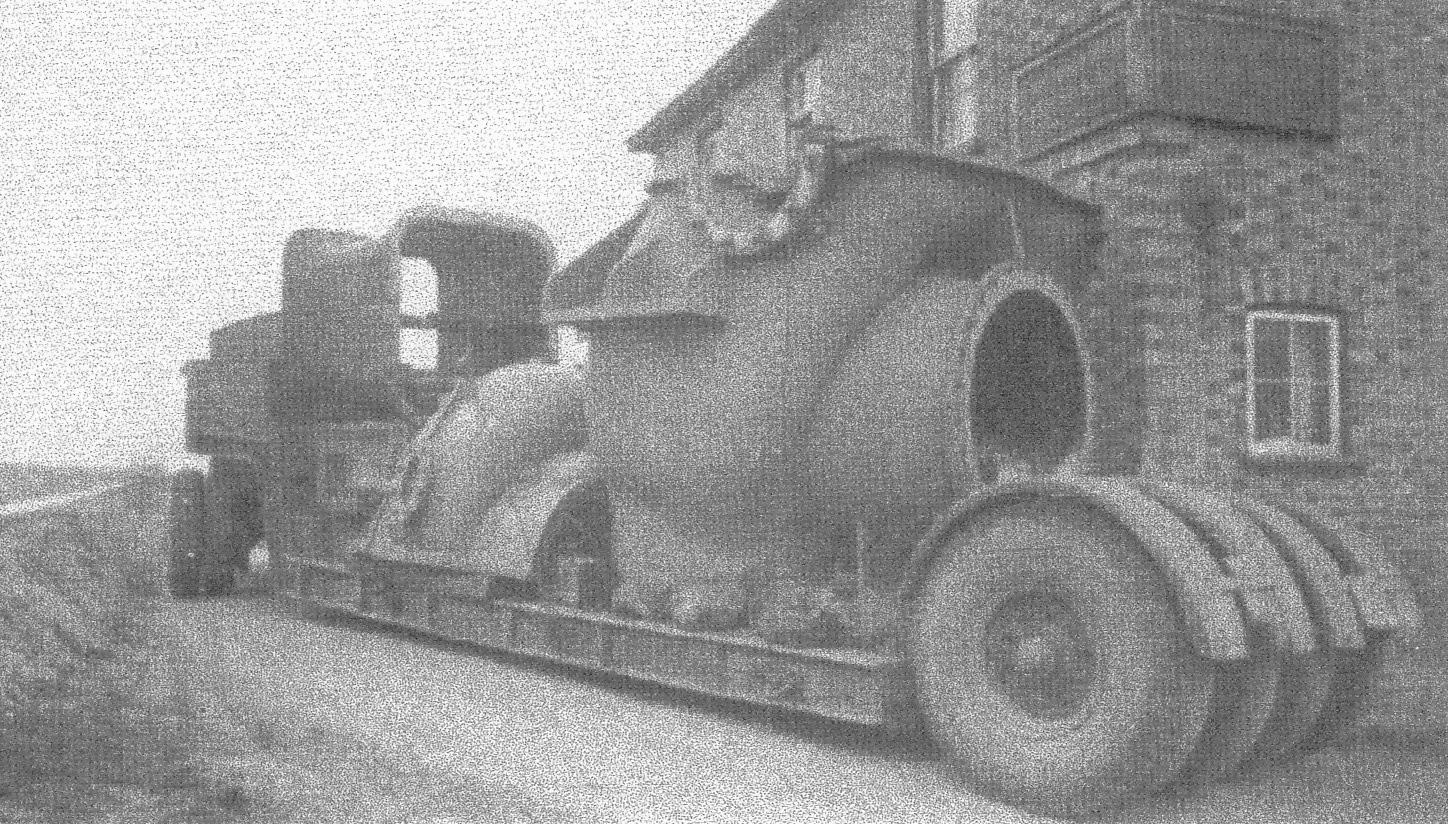
courtesy: John Baker, EA Engineer, Prickwillow
March 1948, first load of pumping machinery. Half a pump on low loader trailer being negotiated round the right-angle turn at the Ship inn, Purls Bridge
Installed in 1949 and seen here in 2011 still operating 63 years later was pump-set number 2:
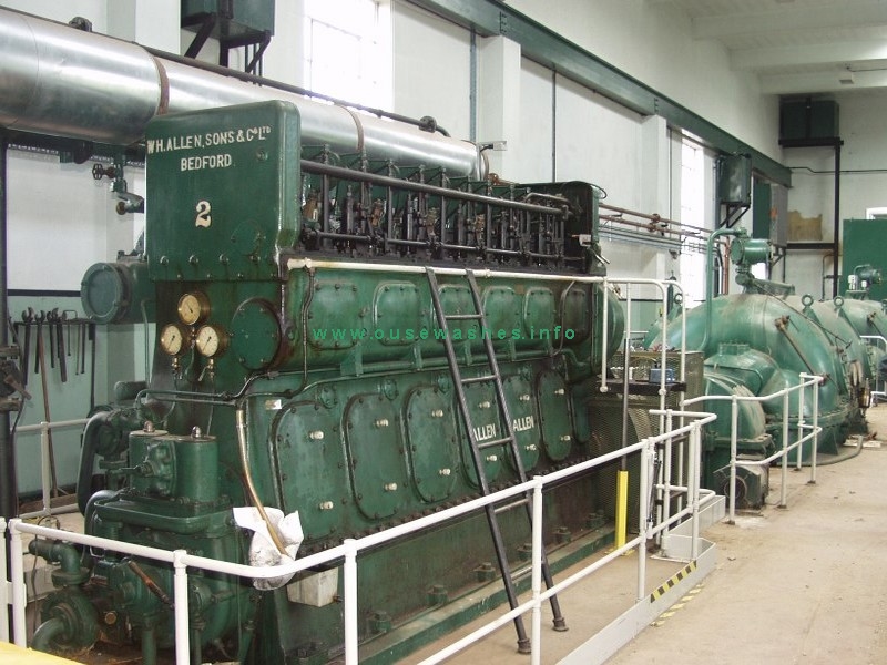
Photo: Internal Fire Museum of Power, Wales
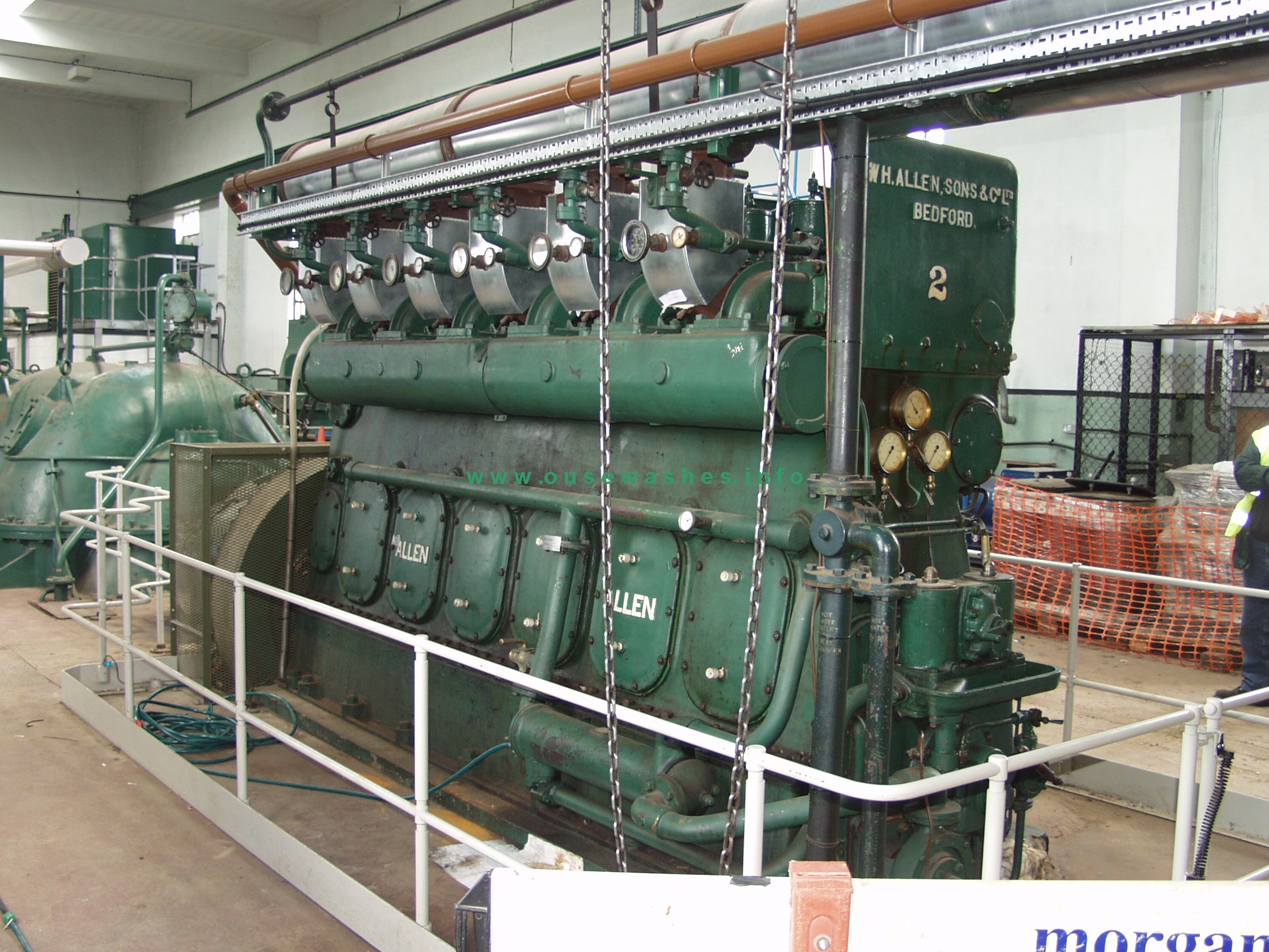
Photo: Internal Fire Museum of Power
The Number 2 Allen engine in 2011 just prior to removal after 63 years service. (It was donated to the Internal Fire Museum of Power in South Wales where it was rebuilt and now exhibited.)
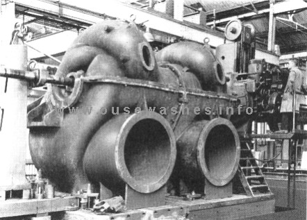
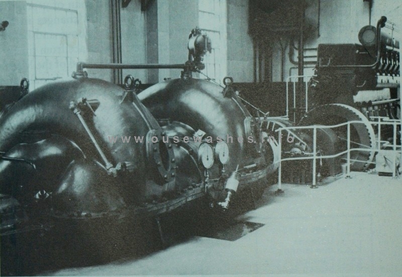
Photo: Bedford Pumps Ltd Photo right: KSG Hinde, "Fenland Pumping Engines"
The visible sections of the pumps - the huge inverted "U" shapes - looked pretty impressive, but there was much more hidden out out sight. Above left, Number 1 pump seen in the factory, on the right after installation.
The suction intake parts on the other side of the pump went down into a sump below the west side of the building filled by the Old Bedford River; the twin 45 inch discharge pipes seen on the left photo above were below floor level when installed and there branched together into a 72 inch pipe, all cast into into the concrete foundations.
Main pump hall (engine room)
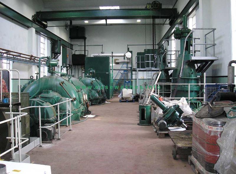 Photo: Environment Agency
Looking northeast in the pumping hall. The intake side is on the left. On the right are the two electrically operated Blakeborough 72-inch sluice valves. and an 18kW diesel-engined generator set (part dismantled?).
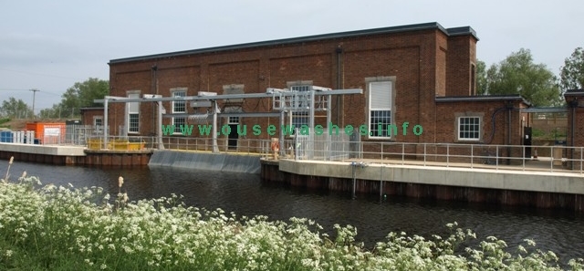
Discharge out of the pump hall was controlled by the two tall electrically-driven sluice valves by the right hand wall. The two 72" pipes then went through the barrier bank discharging into the River Delph via manually operated flap gates controlled from a small brick building (below) on the Delph side of the bank.
Discharge valve house
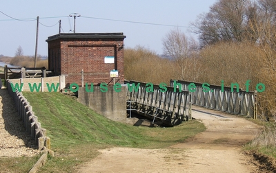
Photo: Peter Cox, 2006, FinePix F810
The Bailey Bridge gives access to RSPB hides on the barrier bank.
The "hidden" parts
The drawing below shows the hidden parts - the sump below the pumps, the pump intake, discharge pipes and the sluice valve in the pump house and flap gate in the smaller building. (The general arrangement is similar in most pumping stations)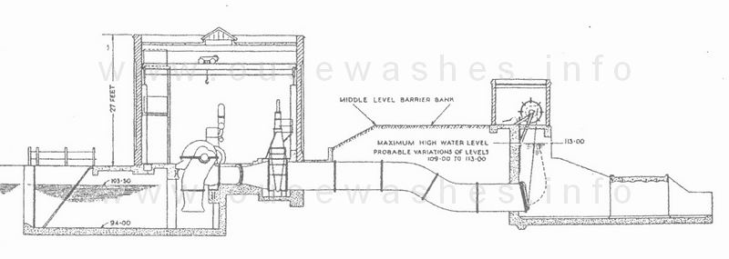
drawing from the The Allen Engineering Review, Feb 1949, (Courtesy of John Baker, EA Ely)
Note that the bottom of the sump here is shown as "94.00" and the water level as "103.50". These are measurements in feet above South Level Datum (SLD) which is 100 feet below the normal Ordnance Datum (OD). The sump bottom is therefore minus 6ft OD, (ie 6ft below sea level). The water level figure shown is that at which the station starts pumping. The bottom of the pump intake is not shown, but it is elsewhere as 97.50 (ft SLD).
Translating the figures to modern terminology, metres OD, the level at which pumping started was 1.15, and it stopped (I believe) at 0.75. In 2002 those figures were reduced by 5 cms (2 inches) to 1.10 and 0.70, perhaps allowing for a lowered bank height?
Total pumping capacity was the sum of the three sources mentioned above - 750 tons (nearly 168,000 gallons) per minute. Those figures give much more indication of their power to the lay-person than the modern equivalent expression of 12.6 cumecs, a "cumec" being 1 cubic metre per second. (Note, not 10 cumecs as sometimes quoted).
1990s costly operation & breakdowns
Refurbish or new station?
During the mid 1990s, a number of costly breakdowns of the ageing plant, plus the high cost of manual operation of the station (two men on duty at all times) led to an appraisal of the flood defence of the river system by consultants Binnie Black and Veatch (BBV) for the body then responsible for the river, the National Rivers Authority (NRA). Options considered including new pumping stations elsewhere.
Electrical power ruled out
due to the high cost of bringing in supply-lines, high standing charges and need for power-failure back-up. The capital cost was put at £1.1 million.
1996 favoured option
new automated diesel plant
A total replacement of the existing plant by four fully automated diesel-powered pump-sets with the same total capacity as the two current pumps but with greater flexibility and security during down-time.
However, the 1996 plan was apparently dropped, whether or not due to the management changing from NRA to EA, I know not, but suspect it was.
1998 Refurbishment, one engine replaced
In 1998 the station was simply "refurbished" at a cost of £248,000, the majority of the cost being replacement of the Allen engine of number 1 pump-set with a new auto-controled Perkins 4006TG diesel contained within a tall metal cabinet seen at the far end in this photo. This was rated at 456hp and ran at 1500 rpm, much faster than the Allen, so requiring a reduction gearbox before connection to the original Allen twin-pumps.2003 more problems, both engines failed
In January 2003, only five years after the 1998 works, "both pumps failed" costing £105,000 for temporary pumping.An EA publication in 2004 stated"highlighting the fact that the design configuration of the plant was complex, requiring a numberof critical plant items working in series for a pump to start."Another problem was a spillage of 6,000 litres of diesel in 2007 due to a pipe failure.
Oh dear. One of the EA's duties is to safeguard watequality and prosecute polluters!
The saga continues below, but first a tabulated history:
Potted history
| period | engine: make model, type, fuel | rating hp | pump | tpm | m3/s note 9 |
acres drained |
discharge/remarks/other | refs |
| 1948-2011 | Allen 6S37C 6 cyl vertical 4 stroke diesel |
410-500 bhp | No. 2 set: Allen Conqueror 2 x 45"centrifugal twin-parallel branched to 72" |
375 | 6.3 | This engine donated to the Internal Fire, Museum of Power, Ceredigion, Wales | ||
| 1948-1998 | Allen 6S37 6 cyl vertical 4 stroke diesel |
410-500 bhp | No. 1 set: Allen Conqueror 2 x 45"centrifugal twin-parallel branched to 72" |
375 | 6.3 | engine of No 1 pump-set sold 1998, replaced with new Perkins | 5 | |
| 1998-2011 | Perkins 4006TG 6 cyl vertical 4 stroke diesel |
456 bhp | No.1 set: Allen Conqueror 2 x 45"centrifugal twin-parallel branched to 72" |
375 | 6.3 | The Perkins had automated starting & drove the original 1948 pump via a reduction gearbox. This was the main pumpset. | ||
| 2011 | 4 x Bedford Electric, each 2.5 cumecs |
Axial flow | 10 | a reduction of 20% from the 12.6 m3/s of the 2 diesels |
New Electric powered plant
The Plan
Following another expensive appraisal in 2004, and the EA's Cranbrook/Counter Drain strategy report of 2008 both of which which considered all the earlier options, and others, the EA decided to "upgrade" and refurbish the pumping station in a £3.4 million project changing from diesel to electric power.This would give the station another 25 years life after which it would be de-commissioned and flood risk managed through flood storage reservoirs utilising mineral extraction pits.
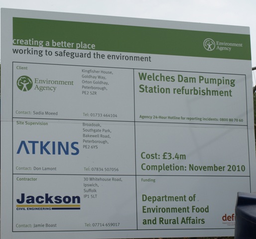 Notice Board showed the main players, cost and due completion date, Nov 2010.
Jackson Civil Engineering main contractor and Atkins as consultants and providing site supervision. Photo: Peter Cox
Suprisingly, Bedford Pumps Ltd were not credited on the board yet had the very major role designing and manufacturing the pumping sets, supply of controls, instrumentation, ancilliary equipment and a stand-by diesel generator.
The existing standard of protection, 1 in 25 years (4%) would be maintained and the new plant would improve reliability and being fully automated, operational and maintenance costs much reduced.
The change to electricity seemed a little odd to some as all the reasons for rejection in 1996 still applied including the cost of electricity being higher than diesel. Somewhat worryingly, the 4 new pumpsets had only 80% the capacity of the diesel, and only 72% of the maximum combined discharges of the two IDB's.
In addition to manufacturing the four new 2.5 cumec Axial Flow pumpsets and siphon breaking valves and associated equipment, Bedford Pumps also supplied the discharge pipework.
The Work
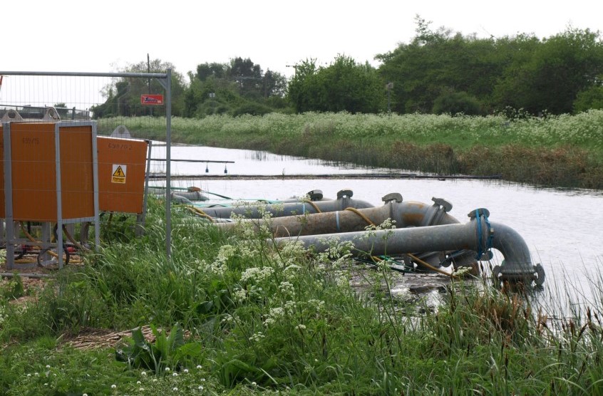
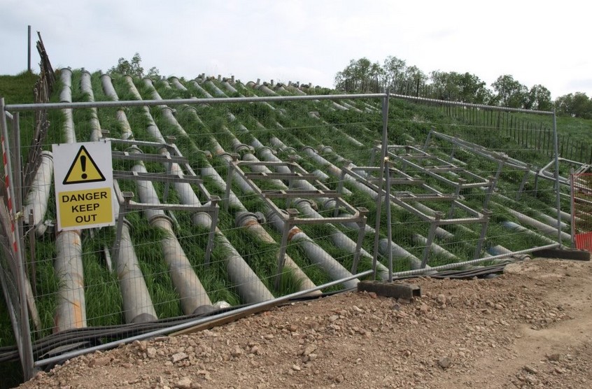 The work involved taking the station out of commission whilst all of the existing plant was removed so temporary pumps were installed down stream of the site.
Upstream, a large pontoon raft had been assembled
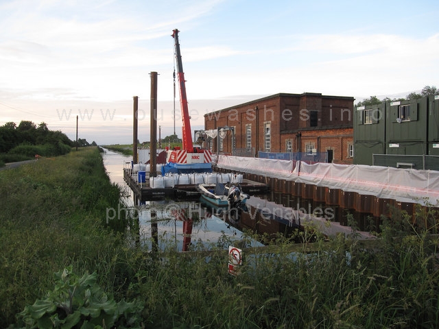 Photo: Hugh Venables, Geograph.org.uk, Aug 2010
Hi-tech hydraulic tracked crane on pontoon raft dealt with most of the heavy lifting. In 1948 the crane was very low-tech
Removal of the diesel engines was relatively straight forward, but had to be stripped down to enable removal through the doors. Pump removal was not so easy because the pump volutes had been cast into the concrete floor. The new electic powered pump sets had pipework designed with siphonic recovery and siphon loop all within the station to avoid that problem.
Electricity supply
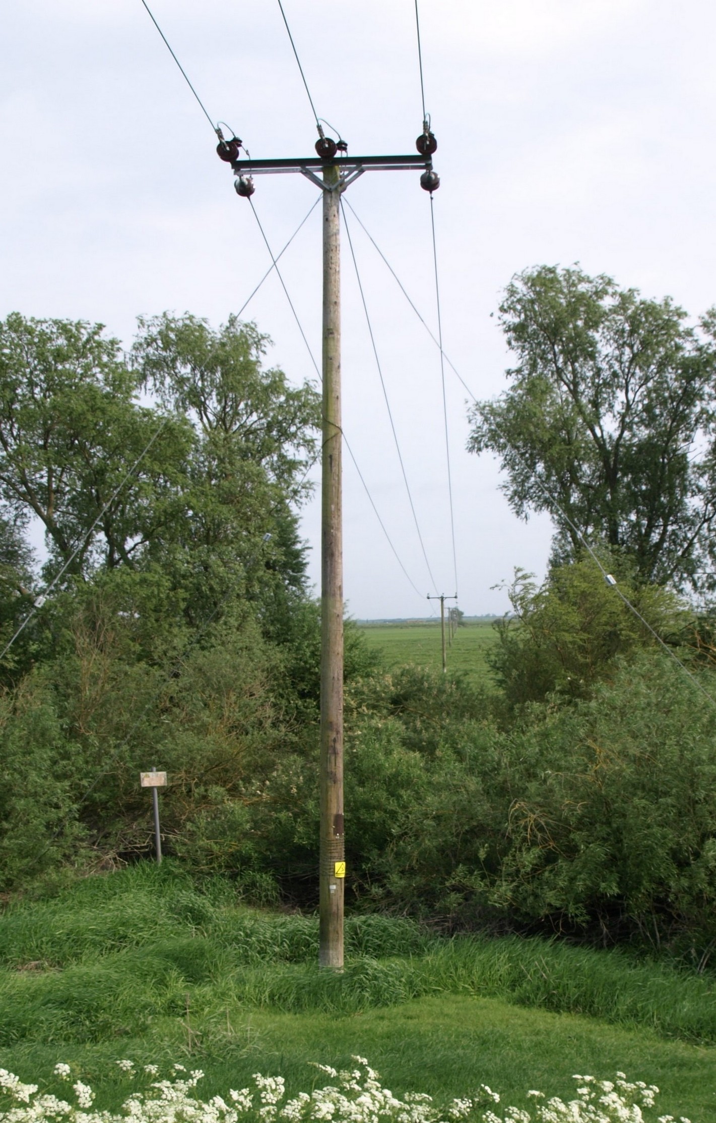
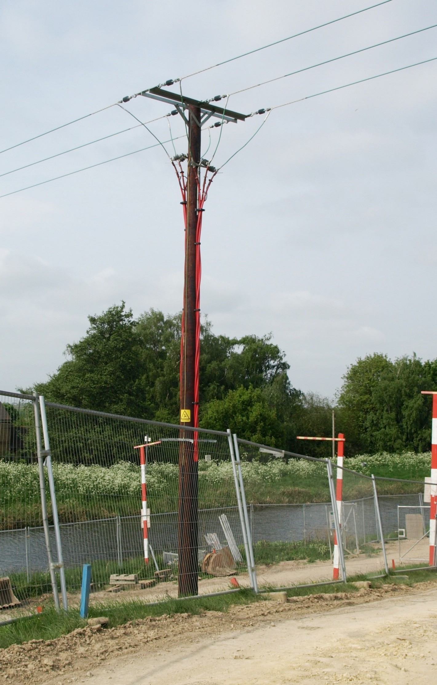
 The line comes over the Washes from Ely (left). In autumn 2009 EDF Energy upgraded it to 11kV-400V, the standard secondary distribution voltage and installed a new pole on the bank (right) from which underground cable was laid to the station's new 1,000kVA transformer at the NE end of site.
When the EA were challenged about the reduced capacity, they said the supply had been upgraded to the maximum possible which was sufficient for only 4 pumpsets.
Thinking of that during this 2025 page revision, I checked the current EDF supply lines and they carry the standard secondary distribution voltage of 11kV-400V. If that was the same as in 2010, then the mains supply was not the limiting factor, it was the rating of EA's specified transformer, 1,000kVa.
Other works included replacing the original steel Crittall windows with 70mm white PVC-u double glazed units, Georgian insert and aluminium louvre panels by SEHBAC Commercial .
By September 2009 JCE had:
- Strengthened the Bailey bridge on the discharge side of the pumping station
- Installed a platform and ducting for the transformer base in preparation for EDF energy to upgrade the power supply in autumn 2009
- Completed indoor modifications necessary for the power supply to be directed to the new pumps.
By January 2010 EDF Energy had:
- upgraded the power supply with 11kV-400V, delivered and installed the 1,000kVA transformer (autumn 2009)
- completed their remaining tasks, laying the new cable, fitting a new pole and activating the new supply
Other work by JCE:
- put in place mitigation measures around the sump and outlet areas to prevent access to nesting birds.(Feb 2010)
- Refurbishment works, May-Sep 2010
- Removal of the 2 diesel engines, pumps, fuel pipe work, day tanks and associated control systems
- Installation of four new Bedford 2.5 cumec axial flow pumpsets, syphon breaking valves, and discharge pipework. Despite claims at the time that the pumps would provide same capacity as the diesel plant, it was only 80%.
- Installation of motor controls and switchgear for the new pumps
- Installation of a new diesel standby generator with switchgear and fuel system.
- Replacement of the overhead gantry crane, the weed screen, and automatic screen cleaner.
- River bank piling works.
- Repair works to the main pump house roof.

Photo: Peter Cox, 2013
The four new electric motors and pumps.
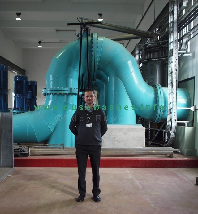
Photo: Peter Cox, 2013
EA Engineer John Baker, a tall man, giving indication of size of pumps
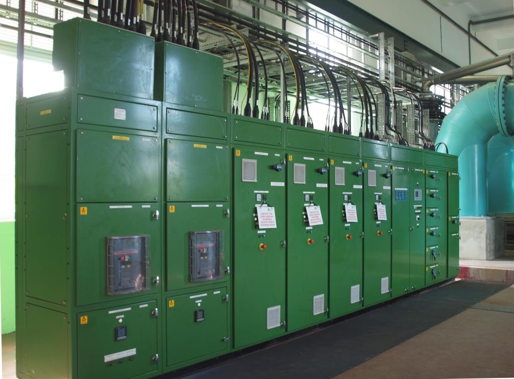
Photo: Peter Cox, 2013
main control cabinets
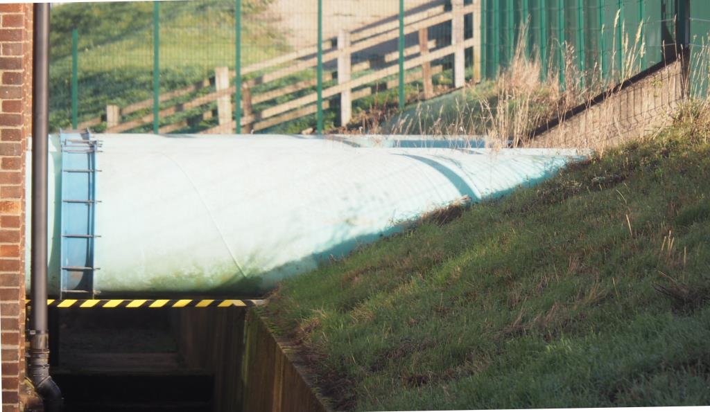
Photo: Peter Cox, 2013
Pipes out at rear 1
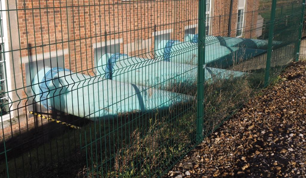
Photo: Peter Cox, 2013
Pipes out at rear 2
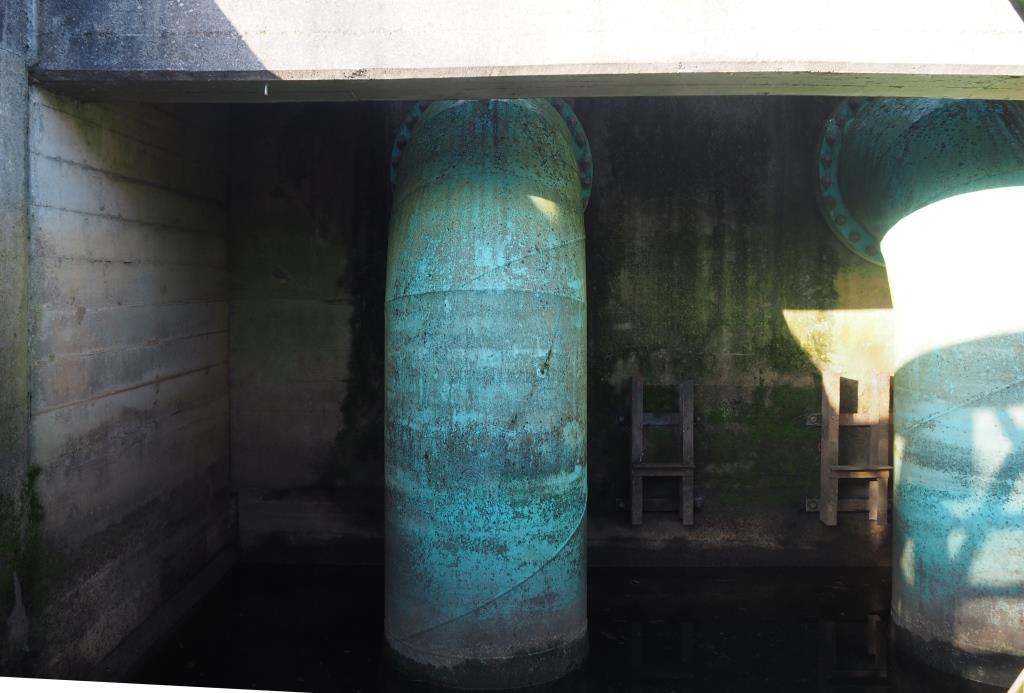
Photo: Peter Cox, 2013
Pipes into river
Stand-by generator
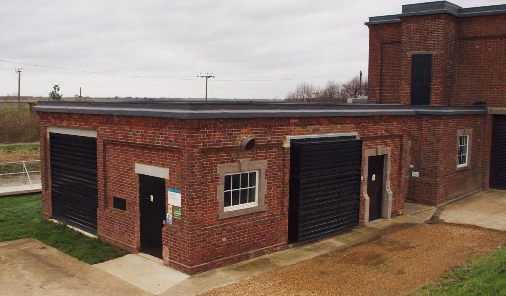
Photo: Peter Cox, 2013
Stand-by generator building at SW end of site was the oil storage building in diesel days

Notes, sources and bibliograhy
Sources: Minutes of the EA Regional Flood Defence Committee Meeting Jan 2010, pages 38 and 39: Bedford pumps news bulletin.| ref | notes, sources and glossary used in text and tables throughout this page |
| 1 | 2004 Cranbrook Drain/Counterdrain (Welches Dam) Strategy Study, SEA8 Scoping Report, by Atkins for EA |
| 2 | 2008 Cranbrook/Counter Drain Flood Risk Management Strategy, Appraisal Report |
| 3 | 2002 Ouse Washes Water Level Management Plan, by Halcrow for the EA |
| 4 | 1949 The Allen Engineering Review, Feb pp 6-15 (copy courtesy of John Baker, EA, Ely) |
| 5 | John Baker, Operations Engr, EA, Ely |
| 6 | 1996 Counter Drain Flood Defences, Gt Ouse LFDC inspection, May, Executive Summary of Appraisal Report (the appraisal was by Binnie Black & Veatch for NRA) |
| 7 | 1997 Welches Dam PS Engine Replacement Project Appraisal Report |
| 8 | SEA= Strategic Environmental Assessment |
| 9 | m3/s = cubic metres per second, commonly called cumecs |
back to potted history
River Level
The "target level" for the Counterdrain/Old Bedford is set by a Water Management Plan. In 2002 it was 0.91m AOD.
If it rises to 1.1m, usually due to floodwater being pumped up into it from the two IDBs, the pumps at Welches Dam Pumping Station (photo above) are automatically start up, pumping water out and into the River Delph/Ouse Washes.
Note, both levels may have been reviewed since