The
|

|
Welcome to my independent research project on
at
Hover Train (Tracked Hovercraft) Experiments, Earith-Sutton Gault
DRAFT, REVISION 14, Sept 2024
Introduction
Three-quarters of a mile south of Sutton Gault there is a curious feature of the Washes. The barrier bank of the Old Bedford River has a large loop or kink in it known as "The Gullet".
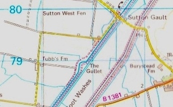
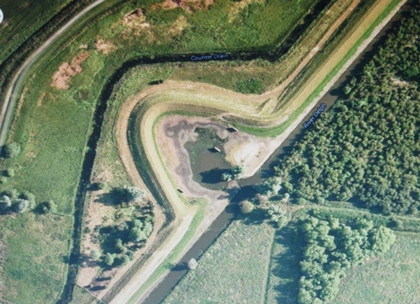 images: map: OS; satellite view: Google
An Illustrated Talk
I have now made the subject of this page into a slideshow talk with much additional material about the pre-Washes work, and many images and information not shown here.
For details, and other talks available, go to my
talks page
 images: above:map: OS; satellite view: Google;
right: Peter Cox (aka Eddy) Aug 2013
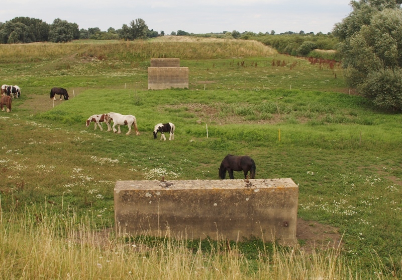
The bank goes round an often swampy area known as "The Gullet" in which are three vertical concrete slabs standing in line while the Old Bedford River keeps to its dead straight course. The slabs can be clearly seen on the Google satellite image and this photo.
(The small river going around the west of the loop is the Counterdrain.)
The casual observer may wonder what the slabs are, or were, and why the bank goes round them.
In fact the loop and the slabs are unrelated, apart from location.
The loop pre-dates the slabs by more than three centuries and was a bank repair following a breach. The bank engineers of the mid-17th C found the land under the breach was porous, and moved the new bank to firmer land.
Darby1 attributes the name to old dialect for a breach - "gull" - and says that there is reference to a Gull "neer Tubbes his howse" in the Bedford Level Corporation's account's for 1655. Today there is a Tubbs Farm half a mile west of the Gullet (see map).
The slabs go back to 1969 and are concrete piers that once supported an elevated concrete "guideway" track planned to run between Earith and Sutton Gault on which an exciting British scientific and engineering invention, a 'tracked hovercraft', popularly called a "Hovertrain", was to be tested running at near-airliner speeds.
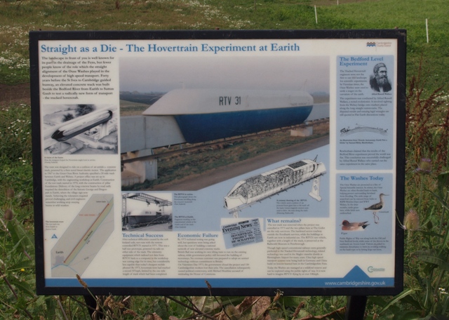 Luckily for inquisitive walkers, Cambridgeshire County Council erected an information board at the Gullet
a few years ago which has some interesting, although not entirely accurate, information about the hovertrain experiments, but
strangely not about The Gullet itself.
 The site of the board is also strange, being at ankle level to those on the footpath, and on a steep slope making closer inspection difficult, as my friend and fellow local historian Chris Holley demonstrates below. It is also furthest away and facing away from Sutton Gault from where most walkers approach.
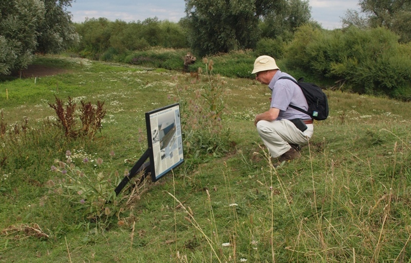
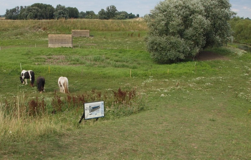 photos above: Peter Cox (aka Eddy) Aug 2013
I'm Peter Cox, although when I started my researches and this page in 2012 I did so under an alias, 'Eddy Edwards'. That was so I could engage with others without interference from someone who I'm sure would atempt to hinder my efforts as he had with another of my websites. Having gained the respect of everyone I've met &/or corresponded with, I happily dropped the alias in 2017 but it wll take a while for all my contacts and web pages to be updated.
My interest in the Hovertrain came about due to another interest, the history and operation of the Ouse Washes through which the Great Ouse River flows en-route to the sea.
In 2012 whilst using Google Earth on my PC following the line of the Old Bedford River, I came upon The Gullet and the concrete piers. I was told the piers were virtually all that remained of "the Hovertrain experiments". I couldn't remember anything about that nor had friends or neighbours and wondered why a piece of Britain's recent history had apparently become forgotten. I soon discovered it certainly hadn't been, in fact the Hovertrain itself had been preserved first at Cranfield for 21 years then at Railworld in Peterborough since 1995. Othe material was acquired and display boards erected summarising the aims and works.
However, the story was not widely known, and there was much still to be told, so I set out to try to fill some of the gaps. Since then many people have added pieces to the story. Some worked on the project or had relatives or friends who had; some lived nearby; another, a French expert on tracked hovercaft worldwide, provided much usefull information. I've also been helped by museum trustees, by videos of old TV films, and by Cambridgeshire historian Mike Petty who supplied contemporary newspaper cuttings and photos which "got me going".
The Archives
Sept 2024 update: (the first for several years.) I refer below to the "bonanza" of finding answers to most of the questions no one had been able to help with. I have recorded that very important find in detail below as it probably hasn't been done so elsewhere.
| 2015 | I discovered from Jerôme Tillier, a French authority on tracked hovercraft worldwide, that a huge amount of original douments of Tracked Hovercraft Ltd ("THL") the company who undertook the Hovertrain project, was in store near Gosport and largely untouched since being acquired. (I later discovered that they had been there prior to 2008, but probably a lot longer, possibly as far back as 1997. |
| 2016 | I suggested to Cambridge Archeological Unit who had been commissioned (with Heritage Lottery funds) to record the Hovertrain project, that they should try to acquire the collection, but no contact was made. |
| 2017 | I joined Railworld as Hon. Hovertrain Achivist and began sorting their collection which had become somewhat dislocated and jumbled. |
| 2018 | Bonanza! With the help of Railworld's Chair of Trustees, Brian Pearce (now 'MBE') I was enabled to "rescue" the archives at Gosport (which were on the verge of being destroyed!)
making two trips in my estate car to do so. The most imported items were deposited at Railworld: the 5 volumes of THL's bound minute books, 35mm film in cartons
and canisters, an A2 size bound book of the civil engineering plans, and 2 huge albums of media reports. Lack of space at Railworld has meant that the vast majority of the THL archives has been stored off-site, with me as hon. curator. Most files appear to have been bundled-up in an orderly manner at Earith in spring 1973 after the Govt closed the project but some unmarked stuff mostly relating to the winding up looks like a quick desk-clearing in London in 1978. I listed the vast majority on spreadsheets, and digitised a number of documents, particularly those relating to the accidents which contributed to the project's demise. after the Govt closed the project, but some unmarked stuff mostly relating to the winding up looks like a quick desk-clearing in London in 1978. I listed the vast majority on spreadsheets, and digitised a number of documents, particularly those relating to the accidents which contributed to the project's demise. |
| 2019 | At Railworld, I completed digitising and catalouging their collection; and I erected shelving on two walls of room 4 for more THL archives, but the arrival of Covid restricted activities then in 2020 domestic duties brought it to a standstill. |
| 2022 | Drew Berry of Fenland on Film began digitising a good deal of the 35mm film and is planning to produce a documentary about the project |
| 2024 | I contacted Drew Berry, and we are now collaborating on the archive work. Drew is taking over the huge task of digitising much of the archives. Due to changes at Railworld, we became worried about the Hovertrain archives stored there. We visited in late August but unable to locate them. Room 4 at Railworld has taken over by Nene Valley Railway. In Sept, we visited again and files had be moved, some to other parts of the building. We eventually retrieved all bar the 5 minute books which could not be found. We are very concerned about these most important documents but have been assured that they have not been disposed of. |
Below I have tried to outline the Hovertrain project and summarise some of the events and features of the experiments, but please note this subject is huge, and this is just a scratch on the surface. In particular, I have not attempted to cover the technology involved in anything other than a simplistic way.
The Project
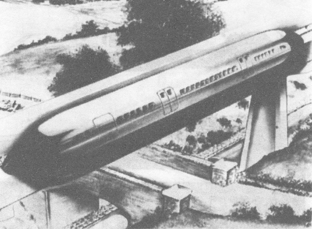 The aim of the hovertrain developers, Tracked Hovercraft Ltd, (THL), a subsidiary of the government agency the National Research
Development Corporation (NRDC), was to provide very high speed (240-300 mph)
inter-city travel on dedicated guideways, with trains (or just a single carriage) transferring or connecting somehow
to conventional rail lines or existing stations. Examples of envisaged journey times from London were 20
minutes to Birmingham, and under 90 minutes to Edinburgh.
The aim of the hovertrain developers, Tracked Hovercraft Ltd, (THL), a subsidiary of the government agency the National Research
Development Corporation (NRDC), was to provide very high speed (240-300 mph)
inter-city travel on dedicated guideways, with trains (or just a single carriage) transferring or connecting somehow
to conventional rail lines or existing stations. Examples of envisaged journey times from London were 20
minutes to Birmingham, and under 90 minutes to Edinburgh.The experiments at Earith by THL built on work by organisations elsewhere during the 1960s, combining the principle of frictionless suspension on a cushion of air (as already used on 'hovercraft') with motive power using magnetism. THL themselves experimented with a scale model over a 300 feet long track near their Cambridge HQ while the facilities at Earith were under construction.
Image: artists impression set in a rural area from Mecanno Magazine
The project ended after only three years due to lack of further government funding. Some say it was lack of vision by politicians, others that it was a pragmatic decision as the idea was impracticable in the UK due to the established rail infrastructure and crowded urban areas which would be better served by British Rail's planned 'tilting' Advanced Passenger Train (which later was also abandoned).
railway horses
Horses hauled the very first trains and still played a part even after steam, diesel and
electric power were introduced.
The last BR horse was retired from shunting duties at Newmarket in 1967, the year this project was founded.
The last BR horse was retired from shunting duties at Newmarket in 1967, the year this project was founded.
Brief Chronology
| year | note | |
| 1967 | Tracked Hovercraft Ltd (THL) formed as subsidiary of
National Research Development Corporation (NRDC), a govt agency, to take over the project from another NRDC
company, Hovercraft Delelopment Ltd, which did initial tests in Hythe, nr Southampton.. £5¼m earmarked for Hovertrain test project. 200 miles of disused railway were said to have been considered as a test site, but the side of the Old Bedford River was chosen [possibly because it was near to the academic centre of Cambridge?] |
|
| 1967 | "Application to Great Ouse River Authority [GORA] specified a 20 mile long track between Earith and Welney." [??] | 9 |
| 1967 July | GORA approved in principle the NRDC application to lease a 20-mile strip of land for 21 years. Test bores showed subsoil can stand the weight of the hovertrack | 18 |
| 1967 July | Prof. Laithwaite, inventor of the Linear Induction Motor, resigned from BR after 6 yrs as a consultant, and joined THL. | 18 |
| 1968 | Earith chosen as the site for a 6,300 sq.ft engineering centre and "hangar" and the start of the line running parallel with the Old Bedford River. | 12 |
| 1968 Mar | Admin and R&D offices set up in Ditton Walk, Cambridge | 12 |
| 1969 June | Construction started at Earith | 21 |
| 1970 | Model vehicle tested on a 300 ft track at Fen Ditton | 17 |
| 1970 June | Construction of one mile of guideway track completed at Earith | 21 |
| 1970 July | a beam failure occured on high-level track. 2 beams & 2 columns lost. "Track laying terminated" | 21 |
| 1970 Aug | A concrete beam "collapsed" [at Sutton Gault] during construction, but eventually sufficient track completed for early trials. | 4 |
| 1970 July | "collapse of some of the track" according to Dr. Bard in evidence to Select Committee 1973 | 20 |
| 1970 July | "a constructional failure" according to Tom Fellows, MD of THL, writing in 1973 | 20 |
| 1971 Jan | foundation faults discovered just ahead of where track being re-erected. (Tom Felows) | 20 |
| 1971 Aug | RTV31 delivered to Earith from Vickers-Armstrong in Swindon | |
| 1971 Dec | First public demonstration of train RTV 31 achieved 12 mph ! | 4 |
| 1972 Feb | Imperial College devised a new form of LIM giving magnetic levitation as well as guidance and propulsion. which worked well on a model, but power too low for full scale use | |
| 1972 June | More powerful motor fitted during 3-week overhaul "Work going on to finish a 2 mile extension". Engineers now said to want a 12 mile track in order to attain 300 mph |
4 |
| 1972 Aug | 72 mph achieved. "More track" (?) reportedly authorised | 4, 12 |
| 1972 Nov | 8 mile total test track now talked of | 12 |
| 1973 Jan | 107 mph achieved | 5 |
| 1973 Feb | Conservative Government abandoned project in favour of BR's APT, the high-speed 'Advanced Passenger Train' (tilting train) | |
| 150 jobs lost due to project closure | 9, 12 | |
| 1973 Aug | Tenders invited for demolition of track | 10,12 |
| 1974 Dec | Earith factory put up for sale | 12 |
| 1975 July | RTV31, the only train built, moved by road from Earith to College of Technology at Cranfield (presumably with one concrete beam) | 12 |
| 1975 | Track dismantled. Metal removed by a company in Cottenham, and concrete by contractors Monk. | 5 |
| 1975 July | Earith factory sold | 12 |
| 1996 | Train and beam donated and moved to Railworld Museum at Peterborough. (Where it still is at time of posting page in 2013) |
see below for sources
The Hangar
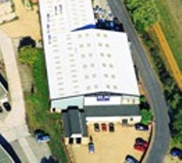
I said at the start that the three concrete slabs (piers) were all that was now visible of the track, but another feature of the project, the heart of the Earith site - the workshops and 'hangar' where the test vehicle was assembled and kept - still exists - although hidden away as shown further down this page.
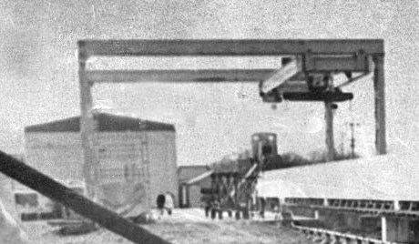
 Above is the rear of
the hangar in 1970 withits door closed. To the right of the hangar is a small peaked-roof shed and behind that is the odd roofline of another
building. Much more about that below.
Above is the rear of
the hangar in 1970 withits door closed. To the right of the hangar is a small peaked-roof shed and behind that is the odd roofline of another
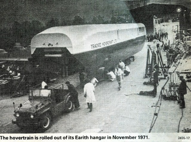
building. Much more about that below.On left the train is on the concreted working area north of the hangar in 1971, having been towed out by an ex-army Austin Champ 4x4. Out of sight to the right is the gantry hoist. The doorway is indicated by the lights inside.
Photos above cropped from press clippings courtesy of Mike Petty
A curiosity
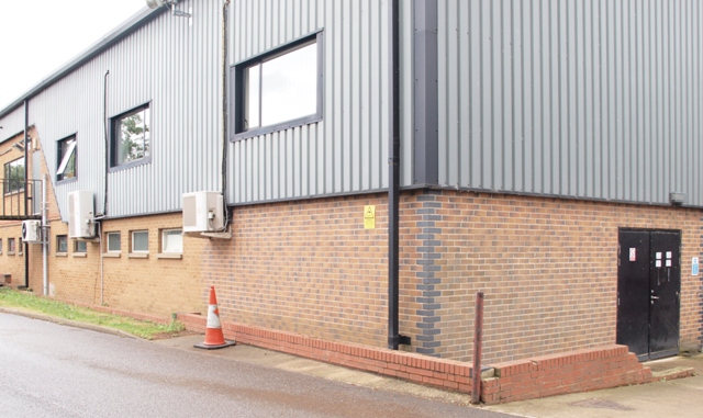
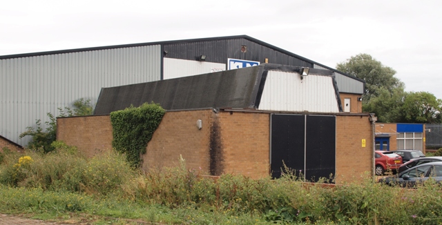 The building in front of the front end of the main building (above, left and below) appears to be as old or even older that the original
hangar and certainly isn't a recent addition as some suggest (confirmed by the factory manager).
 It is about 50 feet long and has an inspection pit, an oddly shaped roof, double doors at the front but none at the back and separated from the main works by about 10 feet of waste ground and bushes. As explained above, in 1970 the main building wasn't as wide as now, and this building (or at least its roof) could be seen from the rear of the hangar as examination of the photo of the hangar and gantry in 1970 reveals.
photo: Eddy Edwards, July 2013
When viewed head-on it has led to some misunderstandings as explained below.
A cautionary note
Copying and pasting other peoples work is common-place on the web. Occasionally I do, but briefly with acknowledgement and comment. To do so without acknowledgement is discourteous, and to do so without analysis of the material is unwise and can simply perpetuate errors. I have posted this section to highlight the problem, not to cause embarrassment.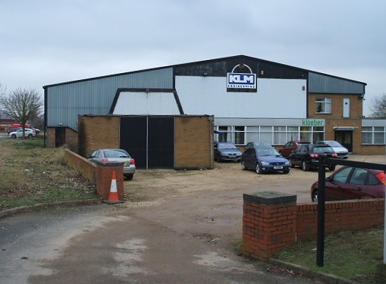
This is the front of the same building shown in previous section, seen in 2010 and taken head-on rather than obliquely as above
The photo is from a Wikipedia article which has since been copied and pasted many times (including by a major Heritage Lottery Funded project).
It was posted in 2010 by Lee Dalton who lives &/or works in Earith who said:
"The guideway ran out of the building towards the camera's viewpoint, curving to meet the Old Bedford River just to the left, out of view. The vehicle entered the hangar through doors that can still be seen as the trapezoidal area on the main building, behind the more recent addition with the black doors."I had to look up "trapezoidal". Apparently its a quadrilateral where one or both sides are not parallel. But I was still baffled by Lee's statement.
- why would oddly shaped doors be needed?
- a look at the aerial view (above) shows this is the front of the building facing south-west away from the track.
- the Old Bedford River is therefore on the right not the left.
- photographic and video evidence shows the guideway did not run into any building either front or back. It terminated in the open on the west side of 'the hangar', the main building, for both operational and safety reasons.
- there is no trapezoidal door (or any other large door) on the front of the main building.
- the "more recent addition" Lee refers to is neither more recent or an addition. It is a seperate building dating to the start of the trials, and at 50 ft long it could not have housed the 72 ft long Hovertain. The roof is an odd shape but I leave it to others to decide if they consider it trapezoidal.
So all those who've used this image without checking have got it wrong too. Moral? DON'T DO IT!!
However, regardless of inaccuracies, we have to consider that the small building with the strange roof may have been used during the experiments. Very close examination of the photo above left captioned "hangar and gantry, 1970", reveals the same strange roof. Was Lee's source correct but there was a misunderstanding about the alignment or what was said ? Or was it just a spoof comment that others have fallen for?
Later note, 2016. Information has been received regarding this building and whether or not it featured in the Hovercraft experiments. I discuss this in my talks.
The Gantry Hoist
This was used to lift the beams for the track during the construction stage, and later to raise the train onto the track. More later.The Track, or Guideway
Introduction
Although it was the train's technology and its futuristic image of high-speed comfortable travel that fascinated people and attracted media coverage, it was the track and the civil engineering feat of constructing it in a restricted area that dominated the landscape, albeit for only a few years, along the south-west edge of the Ouse Washes.Design
During design of the track, computer simulations indicated the problem of vibration created by the train's passage which rippled along the track ahead of the train. Such vibrations were already known and allowed for in bridge and viaduct design, and wasn't a major problem at "normal" vehicle speeds. However, the combination of high speed and the long length of track created a new problem - the train caught up with earlier vibrations and the combination of new and old affected track, train and the land below.The Beams
Dimensions
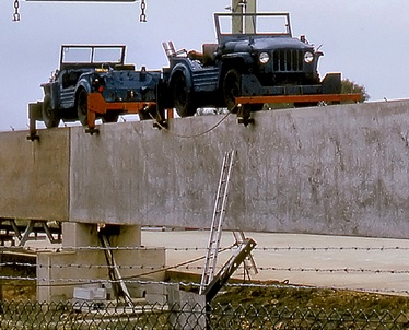 When
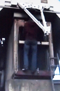
I first began my researches I had to estimate the dimensions and concluded the
beams were in the region of 6 feett high based on a shot (above) from a
video on You Tube11 and approx 4½ feet wide15,
just sufficient to allow ex-army 4x4
Austin 'Champs' to
run on the top (more about Champs
below).
 The ladder has its bottom part hidden, but I estimate it had 12 rungs. At say 10 inches between rungs, the underside of the beam would be about 6 feet above ground, and the top about 12½ feet.
cropped from photo on Flicker by Gordon Edgar3
I later discovered the beams were 75 feet long, 6 feet 4 inches high and 4 feet 6 inches wide. In the 1970s, "imperial" measurements were the norm, even in sectors of the civil engineering industry, and still widely used today in the second decade of the 21st century by older generations of the general public. The metric equivalents are approximately 22.86 x 1.93 x 1.37m.
 Each
beam weighed was in the region of 50 tons17, 9 & 14 and £1,000 each.13
Each
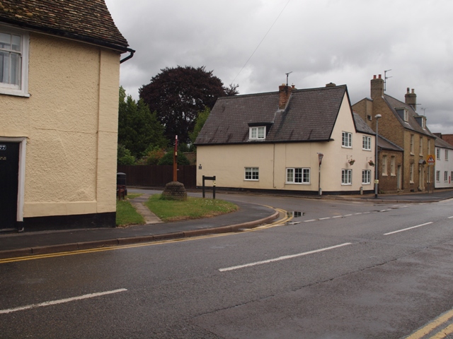
beam weighed was in the region of 50 tons17, 9 & 14 and £1,000 each.13To allow the ultra-long heavy-haulage trucks carrying the beams to turn from Earith High Street into Colne Road (the access road to the hangar location) much of the 17thC George and Dragon pub that stood at the junction had to be demolished leaving just the part on the left. The village sign now stands at the spot.
Photo by Eddy Edwards, July 2013
Construction
Apart from a short stretch northeast of the Hangar, the guideway track ran along a narrow strip of land which in places was only about ten feet wide. On one side was a narrow land drain known as the Counterdrain, and on the other side an access road and a steep bank rising up to contain the floodwaters in Old Bedford River which runs well above ground level.Once the first few beams had been placed in position on the supporting piers and bolted to each other and the supports, each new beam was pushed on rollers along the top of the completed section using a diesel engined shunter. I don't know how the beams were manouvrered into postion at the end of the track, but one photo suggests that the beam was moved into some kind of cradle and cables running from a gantry attached to the far end of the beam. The beam was then pulled and lowered into position while the shunter went back to collect another.
Completed track
From videos, photographs and reports I have seen, and confirmed by site inspections, there were two distinct and quite separate sections of track. One was a mile-long low level stretch starting at the side of the workshops and 'hangar' at Earith running northeast alongside the Counterdrain. This was the section on which the train was tested, with the train towed backwards to the end of the section, then run to Earith. On this section the beams were bolted directly onto concrete piers.The other was a half-mile section of high level track which started just south of Sutton Gault and ran southwest towards The Gullet. Here, there were pylons bolted between the beams and piers to give the necessary elevation.
Practically, in order to run the train at its top speed of 250+ mph, the track had to be dead-straight and therefore it had to go above not around the barrier banks at the Gullet. Commercially, as the aim of the hovertrain system was to whizz through the countryside above existing infrastructure, but coming down to (almost) ground level for maintenance and at stations, it was necessary to test the support design at differing heights for strength, stability and ability to withstand the vibration created by the train's motors, and possibly measure the effects of the train passing over ground-level structures.
At Earith it needed to be low enough to allow the gantry/hoist to raise the train on and off it, and to enable engineers to work on the train m>when on the track rather than in the workshop, at a relatively safe height.
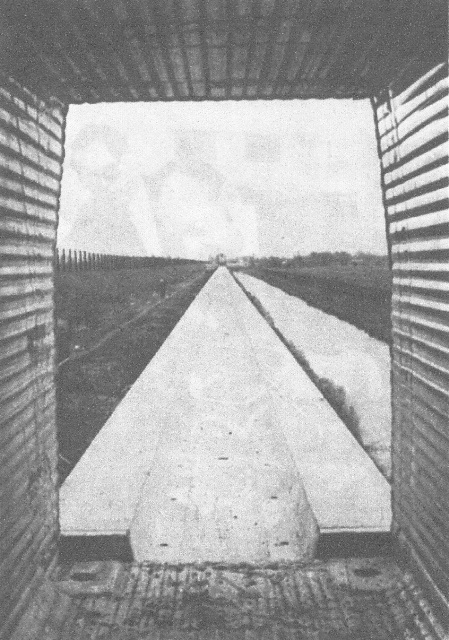
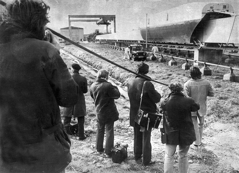 This is part of the low-level section, looking southwest, towards Earith, with the barrier bank of the Old Bedford River just out of
sight on the left. The photo shows a low level section of track supported on concrete piers (the slabs I mentioned earlier),
the hangar at Earith in the distance and a large gantry hoist.
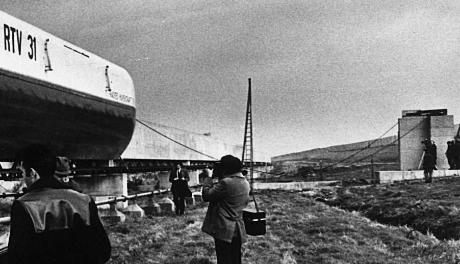
 Note, the train is facing towards Earith, and a wire cable is hanging down through the group of cameramen and up and over the track and a hook at the back of the train. The cable was used to stop the train at the end of fast test runs (see below).
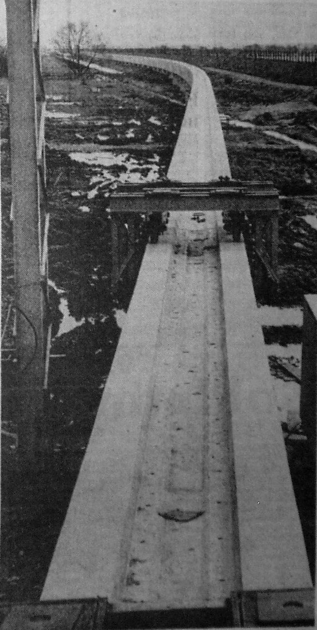 The track clearly does not go into the hangar, but terminates to the side, where the train was lifted and moved sideways with the
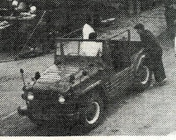
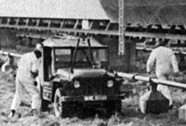
hoist. It was moved in and out of the hangar on rollers, towed by an ex-army 4x4 Austin Champ (NOT a Jeep). That, or another one, is
seen above alongside the track
The track clearly does not go into the hangar, but terminates to the side, where the train was lifted and moved sideways with the
hoist. It was moved in and out of the hangar on rollers, towed by an ex-army 4x4 Austin Champ (NOT a Jeep). That, or another one, is
seen above alongside the trackOn the left, looking in the opposite direction, northeast, is the very start of the track at the side of the hangar at Earith, headed for the Barrier Bank, where it curved and then ran parallel to the bank. The camera has greatly accentuated the curve.
The framework on the track is a "dolly" on which new beams were rolled along to the end of completed track before being lowered and bolted into place. It is not as some think the gantry hoist; one leg of that is on the left.
Note the trough in the top of the beams. This was to accomodate the metal strip that were part of the magnetic motive power.

This is part of the high-level track, looking south-west.
The Barrier Bank and access road are to the left, and the Counter Drain on the right of elevated track. At centre and right skyline are some buildings - a house (Poplar Farm) and bungalow - and a road leading away at right angles. Studying an OS map suggests the road maybe Bedingham's Drove.
I guess this was taken half way between The Gullet and Sutton Gault Bridge.
On the (rail) track is the ex-BR narrow gauge diesel shunter pushing a beam. As this section of track wasn't joined to the southern part, the engine must have been lifted-up onto the track at Sutton Gault.
There is a person on the roadway between the (rail) track and barrier bank who appears to be running away from the camera. Why?
All photos in this section from press clippings kindly supplied by Mike Petty
There were a number of setbacks in construction due to problems with the support piers. A 1970 press report referred to a "collapsed beam". On an internet forum, the Professional Pilots Rumour Network, someone with the username 603DX had worked on the test track in the 1970s and in 2011 he posted:
"My consulting engineering firm were not the designers of that box beam track and its piled foundation piers, that had been done by another firm. We were commissioned to design remedial measures to overcome serious construction defects in several of the pier foundations. I designed a system of underpinning supported by additional bored-in-situ RC [reinforced concrete] piling, then supervised the work to achieve this on site.
Regarding the fate of the short one mile of test track that was built, the local planning and river authorities had insisted that once the research and testing installation had served its purpose, it should be demolished and [the land] restored to the original state."
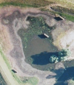 Satellite view by Google
Something which intrigued me when I first looked at this aerial view was the distance between the three remaining track support slabs. From the centre one to the north one is about 70 feet (based on Google satellite data) but double that to the south one. (Update: later measured as 75ft.)
Many similar images had been posted on the internet before I became interested, but nobody had commented on this. I thought it inconceivable that a beam 140 feet long could be transported to site or placed in position, and wondered whether there had been a 4th support in The Gullet.
I therefore organised a visit in company with fellow local history enthusiast Chris Holley in August 2013 to search for any signs of another pier. First, we called on nearby residents who told us that the high level track ran only from just south of the bridge over the Old Bedford at Sutton Gault to, but not across, the Gullet. It was generally believed that parts of the Gullet was so soft some piles did not reach solid ground, and one pier was not constructed.

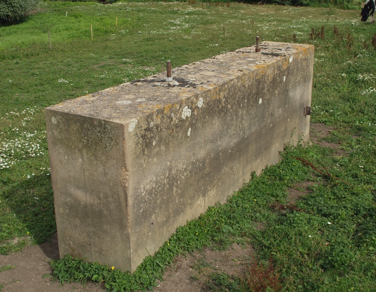 The two outer piers (#4 and #1 on plan below) are 2ft 9ins wide with two studs to connect the metal upper sections; #2 is 3ft 6ins
wide with 4 studs, and the upper and lower parts appear to have been cast at different times.
The two outer piers (#4 and #1 on plan below) are 2ft 9ins wide with two studs to connect the metal upper sections; #2 is 3ft 6ins
wide with 4 studs, and the upper and lower parts appear to have been cast at different times.photos above: Eddy Edwards, Aug 2013
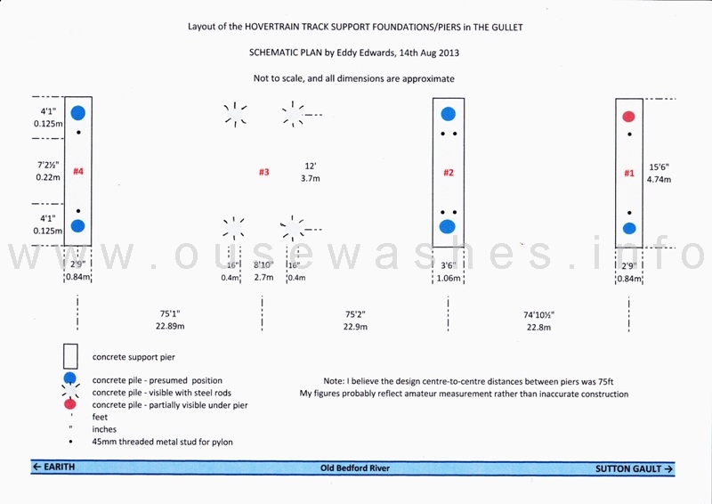 Diagram by Edddy Edwards
Another indication that the two levels of track were separate is found in Hansard for March 1974. In a written answer to a question about dismantling the project, a minister, Mr Meacher, wrote:
"The Tracked Hovercraft Limited facilities at Earith, including the one-mile of usable track, are currently being maintained by the National Research Development Corporation, and no arrangements have been made to dismantle them. A high-level section of track, for which there is no foreseeable future need, will however be dismantled shortly."
The Train
HOW IT WAS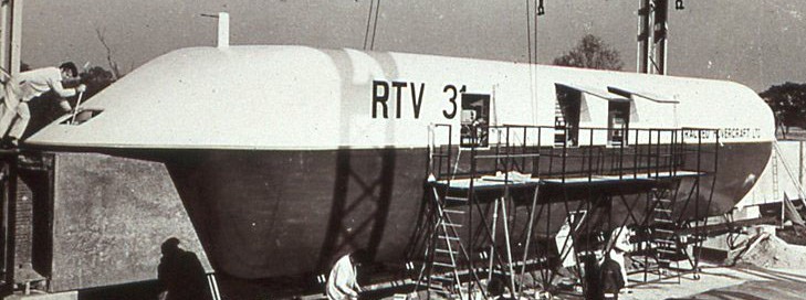
The train being worked on at Earith
Photo courtesy Mike Petty
and seen at speed near Earith,1971
(photo from Cambs CC info board)
HOW IT MIGHT HAVE BEEN

a model at Lee-on-Solent (?)
Photo by Jérôme Tillier
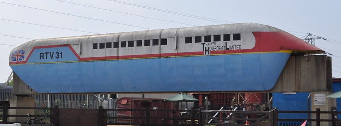
and the actual train at Railworld
Photo courtesy Ashley Dace
The only 'full-size' (? - see below) train built was an experimental prototype named RTV31, the initials meaning 'Research Test Vehicle'.
Propulsion was by a 'Linear Induction Motor' (LIM), a technology developed by Prof Eric Laithwaite which used electromagnets on the vehicle and track to propel and stop it using the principle many of us learned at school, that like-poles repel (which gave propulsion) and opposite poles attract (which provided braking).
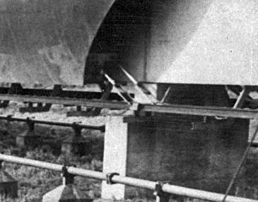
electrical pick-ups at bottom rear of train skirts connecting to power rail
cropped from photo kindly supplied by Mike Petty
LIMs have no moving parts. In a conventional electric motor, a 'rotor' spins inside a static casing, a 'stator'. In a LIM, the 'rotor' is unwound and laid flat under the vehicle, and aluminium plates laid in a recess on the top of the track beams act as the stator.
All that was needed was an electrical current to be connected, achieved here by pickups on the train's side skirt connecting to a continuous power supply rail suspended just below the bottom of the track beams. The interaction of the electromagnetic fields so produced in the train and track produced motion or braking.
The pick-ups created sparks visible during test runs.
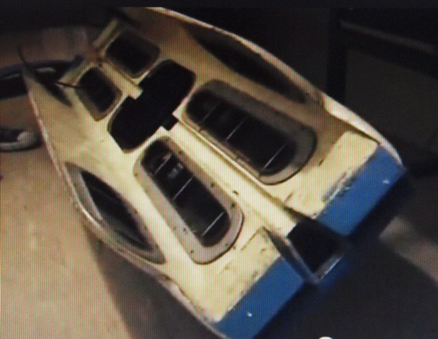
underside of model at Lee on Solent
photo from Jérôme Tillier's You Tube video Inititially the train was lifted in the manner of a hovercraft, i.e. by an air cushion produced by electrically driven fans. One report17 said there were three sets of cushions, one above the box-beam track for lift, and one each side for 'guidance'. That seems to be confirmed by an underside view of a model, left.
Problems pumping air to the pads and the weight of the motors and fans lead at some stage to the lift system being replaced by 'mag-lev', magnetic levitation, resulting in a weight reduction of about 15%, and some energy saving too.
All the reports I've seen are rather vague about this including that of a debate in the House of Lords in July 1973, when Lord Kings-Norton said:
"The hovertrain, which started life as a train propelled by a linear motor but supported by an air cushion, has reached the stage of being a train not only propelled by a linear motor but supported by that same motor by electro-magnetic force."
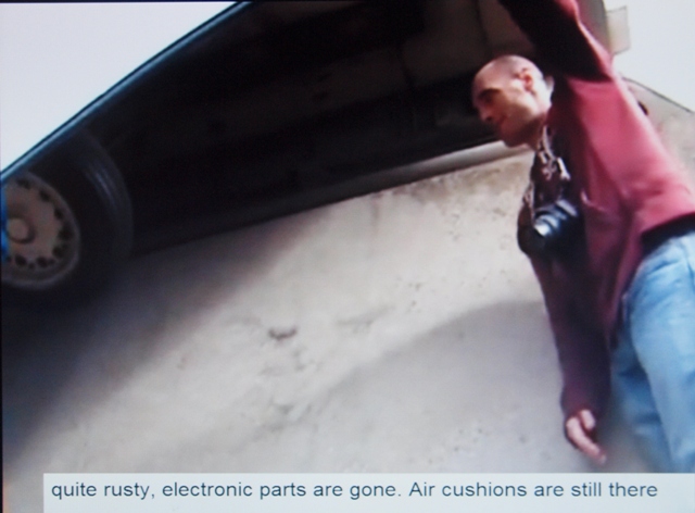
horizontal 'stabiliser' wheels fitted between side skirt and beam
photo and info from Jérôme Tillier's You Tube video shot at Railworld
The interior of the test vehicle contained just the equipment to lift, drive and control it remotely. The was no passenger space in the prototype, but one report suggested eventual 100 seat 'coaches'17. An artists impression (above right) seems to support that, but a model showed a layout with just 13 rows of aircraft-style seating for perhaps only 52 passengers. So were the prototype and model half-length versions? The plan was to run single carriage trains with frequent departures to avoid waiting and to equate to a conventional multi-carriage train running at (say) hourly intervals, which would make the Hovertrain competitive and viable.

view of seating in a modelmodel
Photo by Jérôme Tillier
| Item | specification | notes |
| Length | 73 feet | 5 |
| Width | 12'2" (3.7m) | |
| Weight | 21 tons | 12 |
| Suspension | Initially Air cushion later magnetic levitation |
16 |
| Air pads, which gave 8cm of lift, are still fitted to RTV31 displayed at Railworld | 11 | |
| Motive power | Linear Induction Motor ("LIM"). Very basically, the reaction between a magnet on the train with magnetised track. | |
| Control | remotely by telemetry | 9 |
| Body skin | Wood and Aluminium judging from photos (??) | |
| Seating | ||
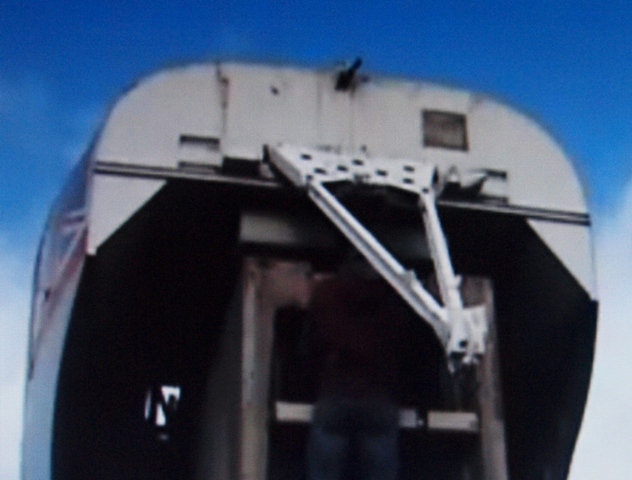
arrester device or tow bar?

arrester hook hanging down.
Click photo to see hook pointing up
photos from Jérôme Tillier's You Tube video shot at Railworld
At the rear of the prototype, a hinged triangular steel frame with a large hook was fitted near the top, see photos on right. Many people say it was a tow bar, and that may have been one of its uses, although the hook pointing upwards as shown here would be far from ideal.
Early photos, when speeds were slow, do not show it; but it was fitted later during high speed runs indicating its real purpose as given on the internet forum mentioned above (the Professional Pilots Rumour Network) in another posting by 603DX, also in 2011:
"If you look at the rear end of the hovercraft test vehicle .... you can see some steelwork sticking up. That was the equivalent of an arrester hook in [aircraft carrier] deck landings, and at the end of the test track there was a navy-pattern arrester wire stretched above the track."The photos and videos I've seen show the test runs finishing at Earith where the arrester cable, concrete anchors and steel lifting pylon were situated. I've not found reference to a reversing facility so the train must have been towed backwards from Earith, possibly using the arrester hook, to the other end of the mile stretch, then run to Earith.
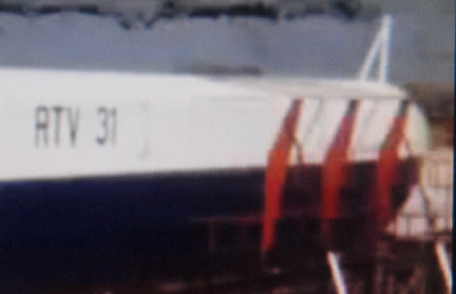
arrester hook deployed up at rear
photo from a video of an ITN news bulletin
Arrester cable slack after use.
The cable went from the concrete anchor block on the right, over the top of the steel pylon and across to the other side of the track.
photo courtesy of Mike petty
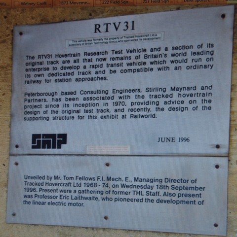
information signs at Railworld
Photo by Ben Sutherland
The train is now on display at Railworld Peterborough, but colourfully repainted with mock windows added and looking quite different to when it was on trial.
Two information plates are fixed to one of the piers. One gives details of the consultants who advised on design of the track, the other commemorates the unveiling in 1996 of the RTV31 exhibit. Those present included Tom Fellows, MD of Tracked Hovercraft Ltd (THL) and Prof. Eric Laithwaite who pioneered Linear Motors.
If you want further details of the history, technology and pros and cons of this and other hovertrains or tracked hovercraft, and/or an explanation of linear motion and magnetic levitation, try Wikipedia (see below).
The Shunter
 The shunter pushing a beam mounted on rollers
from a photo courtesy of Mike Petty A modified narrow-gauge railway diesel-engine 'shunter' was used on the guideway to move new concrete beams to the end of the completed sections of track where presumably there would have been a crane to position the beam onto the next pier.
It may also have been used to tow the train, but I haven't seen evidence of that.
I guess the wheel flanges fitted inside the recess in the beam tops, and it also framework fitted which extended down the sides of the beam to stop it toppling off, and was bright yellow.
The 4x4 trucks
Several small 4x4s can be seen in the photos posted here, four Austin "Champs" and a Land-Rover. They were used to tow the train and for various tasks and other towing duties around the site and along the course of the track.
The Champs were built by Austin in the early/mid 1950s to an MOD specification mostly for the UK forces. I drove several during the 1960s when I was a "part-time" soldier and remember they had a very powerful Rolls Royce 2.8 litre petrol engine, torsion bar independent suspension (no leaf springs), and a 5 speed gearbox with a separate forward/reverse box. But I don't know much more about them. Fortunately, Andrew Wardle of the Austin Champ Owners Club15 does, and he has very kindly examined the photos and noted a number of details and differences.
- The Champ towing the train has longer mirror arms than normal, and wider wheels signified by the white rims. Although Champs do not have a separate low-ratio gear box as on Land Rovers, they do have a very low first gear, and could easily have towed the 21-ton train if it was on wheels
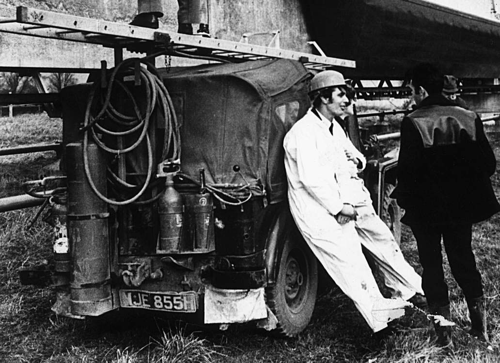
- There are front and rear shots of the one by the track, registration number MJE855H. H would be August 1969 to July 1970 and JE is Cambridgeshire. At first I thought the bottles were part of an oxy-acetylene welding/brazing kit, but on further examination agree that they may possibly be fire fighting equipment. [Note ladder on roof, ladder support on bonnet and ladder against beam.]
- The tyres on the Champs on the beam appear to be overhanging very slightly which would make the beam's external width about 54-55 inches.
If you know any more about the role of these vehicles at Earith, Andrew and I would love to hear from you.
The Concreting plant
The track beams were pre-cast elsewhere and delivered in by road, but other concreting requirements were supplied from an on-site plant. More of which later.
The Power House
Still to be posted.Further sources of information
The residents of Earith and those who worked on the project must have very many memories, tales and photos.The Wikipedia page about tracked hovercraft contains much to interest 'techies', explaining linear motion and air and magnetic levitation. It also has some details of test track construction, and photos and concludes:
"Many original documents from the Tracked Hovercraft project are stored within the Hovercraft Museum library in Hampshire, England, including technical documents, video footage reels, press books and blueprints. A scale model of the RTV 31, a working miniature LIM, photographs, video footage and archive documents are kept within the Museum.[30][31] Another scale model of the RTV 31 is kept within the Railworld museum."
The archives of the late Sir Harry Legge-Bourke (MP for the Isle of Ely 1945-73) held at Leeds University Library contain papers and correspondence about the project.
LIMs are explained at https://en.wikipedia.org/wiki/Linear_motor
Postscript
I seem to have asked more questions than given answers. At the time of posting this latest draft revision, 12th January 2014, I have a couple lines of investigation still open, so there will be more to add and no doubt some corrections to make, but this page will never be any more than just a brief outline of the project.
Some photos are the copyright of the photographers but licensed for reuse here under this Creative Commons Licence
